33
Siemens Building Technologies
Fire Safety & Security Products
10.2008
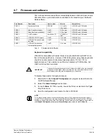
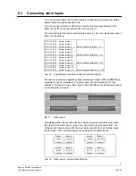
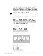
Screen Parameter
Value
Function
VCR/DVR control output
Communications Settings, Channel 3
VCR 2
Multiplexer Settings, Multiplexer 1
Timeout
5
VCR/DVR Settings, VCR/DVR 1
Timeout
5
VCR/DVR Settings, VCR/DVR 2
Timeout
5
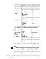
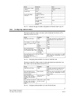
Tab. 18
Example changes to default configuration for VCR/DVR and MPX
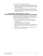
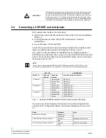
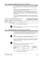
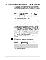
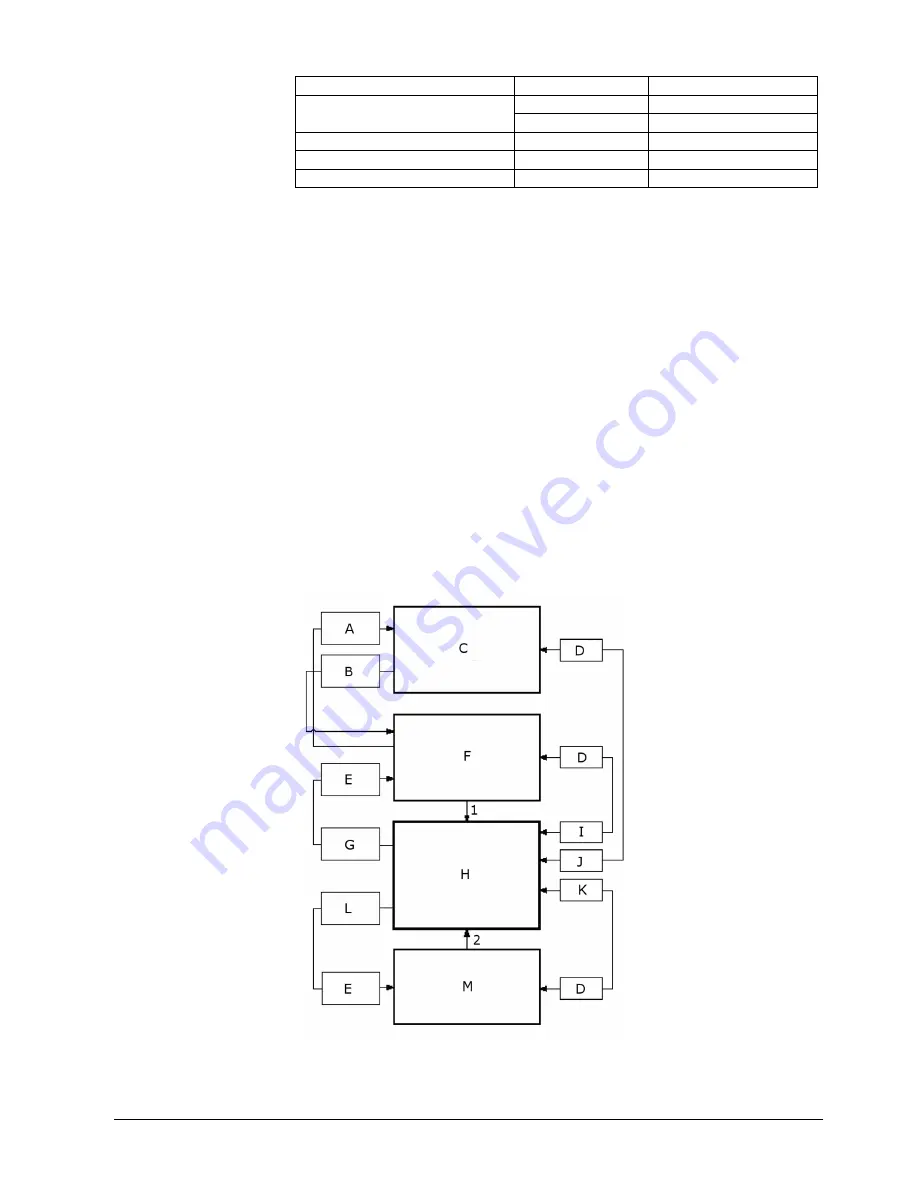
Connecting multiplexer or DVR video outputs to VIS3I-328 video inputs
If required, you can connect the multi-screen or spot outputs from the multiplexer
or DVR to the VIS3I-328 video control input channels (i.e. camera inputs), for
switching to any video output channel (i.e. monitor output).
If you do this, then any text in the multiplexer or DVR video image may overlap with
text injected on the monitor output.
To prevent this, tick the
Blank All Monitor Text
box on the VisiPC (Visilynx3
Configurator)
Camera Settings
screen for each camera used as a multiplexer or
DVR return input. This blanks all the VIS3I-328 text on any monitor to which these
cameras are connected.
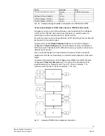
Also, you should disable any C-type telemetry for camera inputs connected to
multiplexers or DVRs, as the telemetry can interfere with multiplexer or DVR video
output.
To disable C-type telemetry, set the
C-Type
value to
Off
at the VisiPC (Visilynx3
Configurator)
Telemetry Cameras
screen, for each port corresponding to the
required cameras (e.g. Telemetry card 1's ports 1–16 serve cameras 1–16,
Telemetry card 2's ports 17–32 serve cameras 17–32, etc).
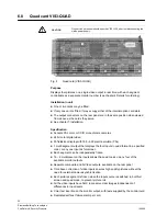
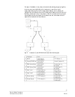
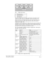
Fig. 12
Example VCR/DVR and multiplexer connection


