background image


21 

Siemens Building Technologies


Fire Safety & Security Products 


10.2008


7 Installation 

7.1 

Installing option cards 


You can add one or two quad cards to each VIS3I-328. Each quad card allows any 
four of the video inputs to that node to be displayed in quad format on a dedicated 
quad monitor video output.  

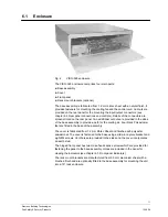
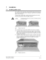
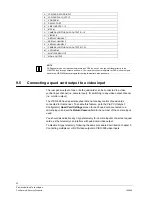
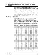
To reveal the two internal option card slots and their card guide posts, undo the 
two captive screws and drop down the hinged front panel. 


CAUTION 

Only service personnel should open the VIS3I-328 unit, after first disconnecting 
the mains power supply. 


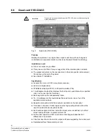
Fig. 9 

Fitting one quad card 

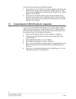
You can install a single quad card (VIS3-QUAD) in either card slot, as follows: 

1. 

A quad card in the slot furthest from the power supply is connected to quad 
output A on the rear panel, and is controlled as monitor outputs 13–16. Note 
that on a single unexpanded unit, these are extra to the eight monitor outputs 
available on the rear panel. 

2. 

A quad card in the slot nearest the power supply is connected to quad output 
B on the rear panel, and is controlled as monitor outputs 13–16. Note that on 
a single unexpanded unit, these are extra to the eight monitor outputs 
available on the rear panel. 


Fig. 10 

Fitting two quad cards 

Summary of Contents for VIS3I-328

Page 1: ...Building Technologies Fire Safety Security Products VIS3I 328 Visilynx 3 Integrated System Unit Installation Manual ...

Page 2: ...document and in the subject thereof By acceptance of the document the recipient acknowledges these rights and undertakes not to publish the document nor the subject thereof in full or in part nor to make them available to any third party without our prior express written authorisation nor to use it for any purpose other than for which it was delivered to him ...

Page 3: ...g VisiPC software 23 8 3 Set VisiPC default product to integrated 24 8 4 Connect and power up the VIS3I 328s 24 8 5 Confirm software versions 25 8 6 Set clock time and perform VisiPC self test 25 8 6 1 Set clock time 25 8 6 2 VisiPC tester and simulator 25 8 6 3 VisiPC self test 26 8 7 Load new configuration as necessary 27 8 8 Load Asian display font data 27 9 System integration 28 9 1 Connecting...

Page 4: ... Software IVM 45 9 8 Clock Synchronisation 45 10 Maintenance and service 46 10 1 Routine maintenance 46 10 2 Corrective maintenance 46 10 2 1 Policy 46 10 2 2 Line replaceable units LRUs 46 10 2 3 Fault indications 47 10 3 System fault finding process 48 10 3 1 Initial checks 48 10 3 2 Diagnostic tool 48 10 3 3 Self test alarms 49 10 3 4 VisiPC self tests 50 11 Disposal 55 ...

Page 5: ...all warnings and instructions marked on the device z Keep this document for reference z Always pass this document on together with the product z It is recommended that all preparatory work e g fitting of accessories be carried out in a workshop prior to final installation Liability claim z Do not connect the device if it is damaged or any parts are missing z Do not make any changes or modification...

Page 6: ...nes The product meets the requirements of the following EU Directives The EU declaration of conformity is available from Siemens Building Technologies Fire Security Products GmbH Co oHG 76181 Karlsruhe Germany EU Directive 2004 108 EC on electromagnetic compatibility Conformity with the European Directive 2004 108 EC is demonstrated by compliance with the following standards Emitted interference E...

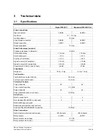
Page 7: ... 567 unweighted 60 dB 60 dB Crosstalk at 4 43 MHz input to input 36 dB 27 dB Video Matrix Single unit 32 i p 8 o p 64 i p 16 o p Text Insertion Text columns per output channel 38 chars Text rows per output channel 14 chars Telemetry Channels C type channels 32 64 C type carrier frequency 11 3 MHz D type channels 32 64 D type fixed termination per channel 120 Ohm Serial Ports RS 232 control ports 1...

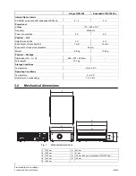
Page 8: ...ck units 3 U 6 U Extra height of mounting feet 7 mm 14 mm Extra width of rack mount brackets 50 mm Weight 8 8 kg 17 6 kg Physical Package Dimensions W H D 560 275 550 mm Total weight 12 7 kg Storage Conditions Temperature 10 to 70 C Operating Conditions Temperature 0 40 C Humidity non condensing 10 90 3 2 Mechanical dimensions 3 2 1 4 5 6 7 8 9 Fig 1 Mechanical dimensions 1 352 mm 6 432 mm 2 365 m...

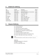
Page 9: ...on Cable 0 30 kg VIS3 KEYCAB S54567 K756 Visilynx 3 Keyboard Cable 0 20 kg VIS3 PCCONCAB S54567 K752 Visilynx 3 PCCON Cable 0 20 kg 5 Scope of delivery z 1 x VIS3I 328 System Unit z 2 x Rack Mount Brackets z 1 x Mains Lead UK Located in packaging z 1 x Mains Lead European Located in packaging z 1 x Data Cable for PC Configuration Located in packaging z 1 x Installation Instruction z 1 x CD for Vis...

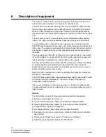
Page 10: ...tputs each quad card makes available the equivalent of an additional 4 monitor outputs The main user interface device of the VIS3I 328 system is the Visilynx 3 keyboard A single keyboard may be powered by a single VIS3I 328 and a further 15 keyboards with local power supplies may be addressed You must not connect a keyboard to both power sources at once Each VIS3I 328 is designed to be used free s...

Page 11: ...re provided in the sides of the base assembly to provide a path for the cooling air Four black Polyastomer feet are fitted in the base of the assembly The cover is fabricated from 1 2 mm Zintec Sheet and finished with polyester powdercoat The cover is fastened to the base using a slide in capture bracket and eight M4 screws Vent holes are provided in the sides and the cover incorporates an earth s...

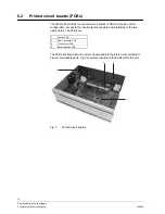
Page 12: ...ol configuration access to the input output connectors and interfacing to the two option cards The PCBs are 1 Control PCB 2 BNC Connector PCB 3 D Connector PCB 4 Slot Expansion PCB The PCBs are fixed within the unit enclosure and are therefore not considered to be user serviceable parts Fig 3 shows the location of the PCBs within the unit 1 3 4 2 Fig 3 Printed circuit boards ...

Page 13: ...power supply fixed on a mounting tray shown above for ease of replacement see chapter 4 Details for ordering NOTE For information on the replacement and the specifications of the power supply module please refer to the installation instruction for VIS3I PSU Specification Input 100 240 V AC 47 63 Hz Output 5 2 V DC 8 5 A 5 2 V DC 4 A Line regulation 0 5 Ripple and noise 1 0 max Dimensions L x W x H...

Page 14: ...y Products 10 2008 6 4 Cooling fan Fig 5 Cooling fan Purpose A fixed speed DC fan that forces air through the enclosure intake vent across the PCBs and power supply and out of the exhaust vent Specification Input 12 V DC Dimensions L W H 80 x 80 x 25 mm ...

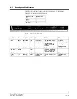
Page 15: ...re connected Unit is Slave Status General Status Red Hardware failure or configuration error Slow Flash self test failure Fast Flash waiting for another VisiPC software component All software components are loaded and self tests have passed Main controller software is running Slave Slave Mode Blue Unit is Slave No Master is connected Unit is Master NETWORK VisiWire Green Blinks when valid data is ...

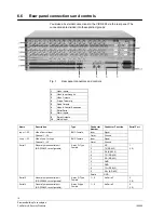
Page 16: ...0 Mains Input Name Description Type Conductor Number Conductor Function Serial Port Inner Signal Input 1 32 Video Control Input Channel 1 32 BNC Female Outer Ground Inner Signal Loop 1 32 Video Loop Through Channel 1 32 BNC Female Outer Ground 1 NC 2 TX RS 232 3 RX RS 232 4 TX RS 422 5 RX RS 422 6 GND 7 GND 8 TX RS 422 9 RX RS 422 Serial 1 General purpose serial port RS 232 422 reconfigurable 9 wa...

Page 17: ... 9 1 12 V 2 12 V 3 NC 4 TX 5 RX DATA_485 6 GND 7 GND 8 TX 9 RX DATA_485 Keyboard Keyboard Control Port RS 422 485 9 way D Type Female Shield GND 10 Inner Signal Output 1 8 Video Output Channel 1 8 BNC female Outer Ground Left DATA Centre DATA Telemetry 1 32 D Type Telemetry Sets of 3 screw terminals Right GND Left NO Centre COM Relay 1 4 Relay Output 1 4 2 12 plug in screw terminal Right NC Inner ...

Page 18: ... Alm_scan7 28 NC 29 GND 30 GND 31 GND 32 GND 33 GND 34 GND 35 GND 36 GND 37 GND Alarms Alarms In from Alarm Panel 37 way D Type Female Shield GND Live Live Earth Earth Mains Power In 3 way IEC inlet Female Neutral Neutral Tab 1 Rear panel connectors NOTE Serial port identification for a Slave expansion Unit is identified in parentheses Name Description Type Positions Left position is Slave Slave M...

Page 19: ...w SW218 5 on their LCD when switched on However VIS3I 328 systems using these keyboards should not enable camera bi directional telemetry alarms 1190 to 1701 for keyboard access These alarms cannot then be handled by PCCON either but VisiPC will show their true states IMPORTANT These earlier keyboards cannot correctly determine whether they are supposed to respond to these higher alarm numbers and...

Page 20: ...nochrome cameras z 24 bit color digital video z 50 fields sec display with 768 625 pixel resolution PAL z 1 multi segment output that displays the four inputs in quad format in a specified order or any one input as full screen z Each segment can be independently frozen z 16 4 multiplexer on the inputs allows the quad to pick up any four of the available monitor outputs z Separate composite and S V...

Page 21: ...nit after first disconnecting the mains power supply Fig 9 Fitting one quad card You can install a single quad card VIS3 QUAD in either card slot as follows 1 A quad card in the slot furthest from the power supply is connected to quad output A on the rear panel and is controlled as monitor outputs 13 16 Note that on a single unexpanded unit these are extra to the eight monitor outputs available on...

Page 22: ... for expansion You can connect two VIS3I 328 units together using a single expansion cable to enlarge the video matrix node to 64 loop through inputs by 16 outputs When you connect two units in this fashion you need to set one unit to be the master unit in the node and connect it to the Visilynx control network 1 Place the units one above the other in a rack cabinet or on a tabletop 2 Connect the ...

Page 23: ...software is contained in the User Manual 8 1 Inspect all items 1 Visually inspect all the units especially all input and output connections 2 Check the contents of the shipping package against the packing note 8 2 Connect a PC running VisiPC software The VIS3I 328 incorporates an RS232 Test Config connector port on the rear panel which allows connection via a 9 way to 9 way interface lead Type VIS...

Page 24: ...ftware User Manual 3 From the Options drop down menu highlight Default Product and select Integrated NOTE This ensures that factory set default data applicable to VIS3I 328 is always loaded when the New option is selected at the File drop down menu 8 4 Connect and power up the VIS3I 328s 1 If you want to connect two VIS3I 328s as a single expanded matrix node you need to connect an expansion cable...

Page 25: ...ilynx main software Visilynx flash boot loader Visilynx configuration Visilynx font 6 You can perform any required software upgrades by selecting the Transfer menu command and then the Software option as detailed in the VisiPC Software User Manual IMPORTANT Any Configuration held in the VIS3i 328 is erased when you transfer the main control software You will therefore need to transfer the configur...

Page 26: ... from all tests since the last power up are retrieved using the Self test Results button Each Self test record consists of a maximum of 5 lines of text including the Pass Fail status of the test and the date and time it was done If the latter are wrong you may need to set the internal clock time as described at the start of this section Results are categorised as follows z Pass The item tested is ...

Page 27: ... parity 1 stop bit Serial Port 3 Communication Channel 3 set to Data Log 9600 Baud 8 data bits no parity 1 stop bit Serial Port 4 Communication Channel 4 set to Debug 9600 Baud 8 data bits no parity 1 stop bit Test Config Serial Port 9 Communication Channel 9 set to V3 Remote Control 38400 Baud 8 data bits no parity 1 stop bit Keyboard Serial Port 10 Communication Channel 10 set to Keyboard Input ...

Page 28: ...onnected Pin 1 12 V Pin 1 12 V Not connected Pin 6 0 V Twisted pair Pin 6 0 V Not connected Pin 2 12 V Pin 2 12 V Not connected Pin 7 0 V Twisted pair Pin 7 0 V Not connected Pin 5 data Pin 5 data Pin 5 data Pin 9 data Twisted pair Pin 9 data Twisted pair Pin 9 data Tab 7 RS 485 keyboard cable wiring In cases where you need to connect a keyboard via a fibre link or through some other device where ...

Page 29: ...2 Port Pin CKA Port COM1A Pin 3 2 2 3 5 5 Tab 10 RS 232 CKA keyboard cable wiring for port 2 The CKA4820 keyboard port configuration switches must be set as detailed in Tab 11 and Tab 12 The menu parameters requiring setting are as per Tab 13 1 2 3 4 5 6 7 8 OFF OFF OFF ON ON ON ON ON Tab 11 SW301 DIP Switch settings 1 2 3 4 5 6 7 8 OFF OFF OFF OFF OFF OFF ON ON Tab 12 SW401 DIP Switch settings Me...

Page 30: ...uence n PTZ Operation Joystick Pan Tilt Zoom Focus Near Focus Near Focus Far Focus Far Zoom In Zoom In Zoom Out Zoom Out F2 Auto Focus on off F3 or Pos Recall Home Preset position F4 Start Preset Tour F5 Wiper on off F6 Press Wash on F6 Release Wash off F7 Lens Slow on off F8 Aux 1 on off n Mem Store Preset n n Pos Recall Preset n OSD Operation F1 OSD on off Joystick OSD navigation F9 Select OSD n...

Page 31: ...Similar for alarm contacts 36 48 PIN 1 to PIN 27 PIN 2 to PIN 27 PIN 3 to PIN 27 Alarm contact 113 Alarm contact 114 Alarm contact 115 Similar for alarm contacts 116 128 Tab 15 Typical alarm connections direct to alarm connector For numerous alarms a separate optional alarm panel Type VIS3 ALARMBOX is available for ease of installation The alarm panel fits into a standard 19 rack cabinet A 37 way ...

Page 32: ... from the Visilynx keyboard or PCCON remote control input then you have to connect the VIS3I 328 serial control ports on the rear panel to these devices using RS 232 cables which must observe the pinouts shown in Tab 17 NOTE Ports 1 3 and 4 are dual standard RS 232 and RS 422 ports while Port 2 is RS 232 only This accounts for the difference shown in Conductor Function See Tab 1 for full connector...

Page 33: ...then any text in the multiplexer or DVR video image may overlap with text injected on the monitor output To prevent this tick the Blank All Monitor Text box on the VisiPC Visilynx3 Configurator Camera Settings screen for each camera used as a multiplexer or DVR return input This blanks all the VIS3I 328 text on any monitor to which these cameras are connected Also you should disable any C type tel...

Page 34: ...5 Connecting a quad card output to a video input The rear panel output of one or both quad cards can be connected to a video control input channel i e camera input for switching to any video output channel i e monitor output The VIS3I 328 has a special keyboard menu for easy control of quad cards connected in this manner To enable this feature go to the VisiPC Visilynx3 Configurator Quad Card Sett...
Page 35: ...using the two rotary hexadecimal switches on the rear panel The left rotary switch sets Sixteens and the right switch sets Units You set the address of a dual unit expanded node using the Master unit address switches To convert between decimal used in VisiPC and hexadecimal for the switches use Tab 19 Decimal Hex Decimal Hex Decimal Hex Decimal Hex Decimal Hex 1 01 27 1B 53 35 79 4F 105 69 2 02 28...

Page 36: ...rol node As above Also at least one port must be configured as a keyboard or PCCON control port 4 8 Tab 20 Serial ports available for networking NOTE If you use the RS 232 PCCON serial port for networking you may need an external RS 232 to RS 422 converter to drive a long serial line 9 6 3 Connecting VIS3I 328 unit nodes using trunk connections An example system interconnection block diagram of th...

Page 37: ...file Full details of VisiPC operation are detailed in its User Manual Fig 13 Example 3 node VIS3I 328 interconnection block diagram Connection From To A Monitor Local Node 3 Monitor Output 1 CCTV Monitor 1 B Keyboard RS485 Data Local Node 3 Serial Port 10 Visilynx 3 Keyboard 2 C RS232 Network Data Local Node 3 Serial Port 1 Remote Node 1 4 Serial Port 1 D RS232 Network Data Local Node 3 Serial Por...

Page 38: ... to default configuration for Local Node 3 unit Screen Parameter Value Nodes 3 Global System Settings Node trunks 2 Function Network control input Communication Settings Channel 1 Protocol VisiWire Name N2 Node Settings Remote Prefix 2 Neighbour Node End Node 1 Neighbour Node End Trunk 1 Local Node End Direction Output Node Trunk Settings Node trunk 1 Local Node End Monitor 8 Tab 23 Example change...

Page 39: ...oard does not require a corresponding keyboard to be connected Ticked Keyboard Settings for the local node keyboard with this number to be given access to the alarm s Alarm Monitors At least one alarm monitor must be non blank does not require a corresponding monitor to be connected Tab 25 Configuring network alarms on a remote VIS3I 328 node The steps required to configure a local node s keyboard...

Page 40: ...rmined by the number of the serial port at the VIS3I 328 configured to control it Also the Visilynx 2 node has no network configuration so the monitors used as trunk outputs are determined by the neighbour node trunk numbers configured at VIS3I 328 Screen Parameter Value Nodes 2 Global System Settings Node Trunks 2 Alarm Settings Alarm Type None for all trunk inputs Function Network Control Input ...

Page 41: ...1 Global V2 Configuration Total keyboards As low as possible to include only the keyboard number set on the 309 card Setting the default 32 keyboards causes network communications to fail due to excessive 309 card user login logout times PIN support Must be enabled for the 309 card keyboard Keyboard V2 Configuration User Timeout Must be zero for the 309 card keyboard Tab 29 Visilynx 2 configuratio...

Page 42: ...cond to indicate it is in bridge mode and is seeing a monitor node If the LED is off check the connections to the monitor nodes and the Comm Channel settings in the configuration s The camera and monitor numbers allocated to a monitor node are determined by which bridge node serial port they are connected to The monitor nodes always have 16 monitors allocated to them to allow for the fitting of qu...

Page 43: ...on changes for bridge mode A controlling four expanded VIS3I 328 remote nodes Screen Parameter Value Nodes 5 Bridge node is always node 5 Node Trunks 4 1 per Monitor node Cameras 256 Total of cameras on all nodes System Monitors 64 Total of monitors on all nodes Alarm 1 64 Alarms on keyboards PCCON Type Trunk or None required to permit trunk inputs below Neighbour Node End Node 1 Neighbour Node En...

Page 44: ...85 is fully supported NOTE Alarm handling and multi hop networking are not supported in bridge mode B The special network address mode used to select bridge mode B is detailed in Tab 34 Bridge Unit Network Address Monitor Node Cams Mons Monitor Node Network Address VIS3I 328 Needed Total Cams Mons B0 32 16 00 5 32 64 B1 64 16 00 9 64 64 Tab 34 Bridge mode B network address settings The PCCON netwo...

Page 45: ...M V3 4 5 or higher using any suitable RS232 serial port Tab 1 details the serial port connections Using VisiPC set the serial port function to Remote control input using the IVM remote control no Bus ID or IVM remote Bus ID Keyboard protocol as required Set the port parameters accordingly 9 8 Clock Synchronisation It is possible to have the VIS3I 328 system time synchronised via any suitable RS232...

Page 46: ...orrective maintenance 10 2 1 Policy A suggested policy to be adopted for the unscheduled maintenance of the VIS3I 328 is z All unscheduled maintenance tasks relate to the removal and refitting of the Line Replaceable Units LRUs identified in Tab 36 z Items considered repairable will be returned to the supplier for investigation and possible repair or replacement 10 2 2 Line replaceable units LRUs ...

Page 47: ...ace connected to one of the rear panel serial ports all alarm events can be read from the data log printout These events include operator actions taken in response to alarms as well as the alarms themselves If a printer is not available the VisiPC software may be used to retrieve the last 2000 alarm and action events using the Show Log button on the Alarm List tab of the Visilynx Tester and Simula...

Page 48: ...s enabled by the system configuration A failure of the 5 V supply causes an inability to start no front panel LEDs lit or in unexpected restarts shown in the Alarm Action Log Cooling fan failures A failure of the cooling fan causes an over temperature alarm 1028 if the alarm is enabled see Tab 37 If a malfunction due to over temperature is suspected the flow of air at the cooling vent holes should...

Page 49: ...ed Control PCB T323 Ignore after loading new configuration Restart VIS3I 328 Unit to check true state If fault persists return to supplier 1028 Internal power supply failure or over temperature Power supply or fan Replace Power Supply Module 1029 I O failure Control PCB T323 BNC Connector PCB T322 D Connector PCB T321 Return to supplier 1030 1061 VCR DVR 1 32 failure VCR DVR Operational not fault ...

Page 50: ...sts Fixed Variable and Default configuration data Do not save results None Re detects option cards Save results to flash None Required if cards have been changed and config data not reloaded Auto detect hardware Tip Saving auto detection results to flash is a quicker way of registering changes in option card positions than re loading configuration data but has the same effect Re detects option car...

Page 51: ...d to camera inputs Video sources must be good quality such as direct camera video Tests video routing from connected cameras to internal monitor outputs Tab 38 VIS3I 328 VisiPC self tests Serial port external loopback connectors The self test external loopback tests confirm that the serial ports are working correctly To conduct this test you need to fit special test plug connectors to each of the ...

Page 52: ...t the D type telemetry ports are working correctly To conduct this test you need to link the D type ports for cameras 1 16 to the ports for cameras 17 32 You do this by linking the two removable screw terminal blocks with pairs of link wires as shown below for the first block of four cameras This pattern should be repeated for the remaining three blocks Camera 1 Camera 2 Camera 3 Camera 4 GND GND ...

Page 53: ...ults 12 V supply Voltage read Voltage 5 V supply Voltage read Voltage VBATT supply Voltage read Voltage SRAM Test Results Static RAM size Memory size detected Size in kilobytes Battery Backed SRAM Test Results Command status data validation None None RTC Test Results Timer interrupt period Period measured Period in ms RTC Register integrity Bad registers Register count and first bad value SCB Subs...

Page 54: ...r always 1 Slot Type Too many cards of one type Card type details Type Number allowed Number detected Valid Flash hardware configuration is different from auto detected one Flash configuration used None None Auto detection test exception buffer full None None Video Routing Test Exceptions Video routing tests passed Total routes tested Total routes tested No input video source detected None None Sy...

Page 55: ...d bin symbol on the product means the product is covered by the European Directive 2002 96 EC The correct disposal and separate collection of your old appliance will help prevent potential negative consequences for the environment and human health It is a precondition for reuse and recycling of used electrical and electronic equipment For more detailed information about disposal of your old applia...

Page 56: ...www buildingtechnologies siemens com 2008 Copyright by Siemens Building Technologies Data and design subject to change without notice Supply subject to availability Printed in the Federal Republic of Germany on environment friendly chlorine free paper Document no A6V10086958 Edition 29 10 2008 ...

Reviews: