

45
Siemens Building Technologies
Fire Safety & Security Products
10.2008
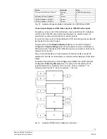
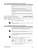
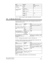
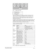
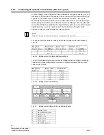
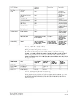
The same system configuration considerations as for chapter 9.6.6 Controlling 256
cameras x 64 monitors (banked switching; not full cross point) (bridge mode A)
apply.
The same sample configuration as in Tab. 33 can be used for bridge mode B with
just the one change of:
Screen Parameter Value
System Cameras
64
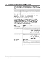
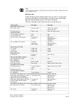
9.7
Controlling via the Video Management Software IVM
It is possible to have a VIS3I-328 controlled from IVM (V3.4.5 or higher) using any
suitable RS232 serial port. Tab. 1 details the serial port connections. Using VisiPC
set the serial port function to
Remote control input
using the
IVM remote control
(no Bus ID)
or
IVM remote (Bus ID=Keyboard)
protocol as required. Set the port
parameters accordingly.
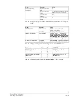
9.8 Clock
Synchronisation
It is possible to have the VIS3I-328 system time synchronised via any suitable
RS232 or RS485 serial port. Tab. 1 details the serial port connections. The
communication protocol is compatible with Time & Frequency Solutions Message
27, as utilised in models M210 and M211. Using VisiPC set the serial port function
to
Clock reference input
. Set the port parameters accordingly.


