Siemens SITRANS FX300 Operating Instructions Manual Download Page 59

 OPERATION 

6

59

SITRANS FX300

www.siemens.com/flow

06/2009 - SFIDK.PS.050.F2.02   A5E02100423

(available if Maes.Inst = 

Mass, see menu item 

1.1.3)

kg

Unit  

...

^

Select totalizer unit for mass flow measurement

0000000000

kg 

...

...

^

Enter preset totalizer value

Reset Yes /

Reset No  

...

^

Reset totalizer

Do not reset totalizer/

Disp. off /

Disp. on    

...

^

Do not display totalizer

Display totalizer /

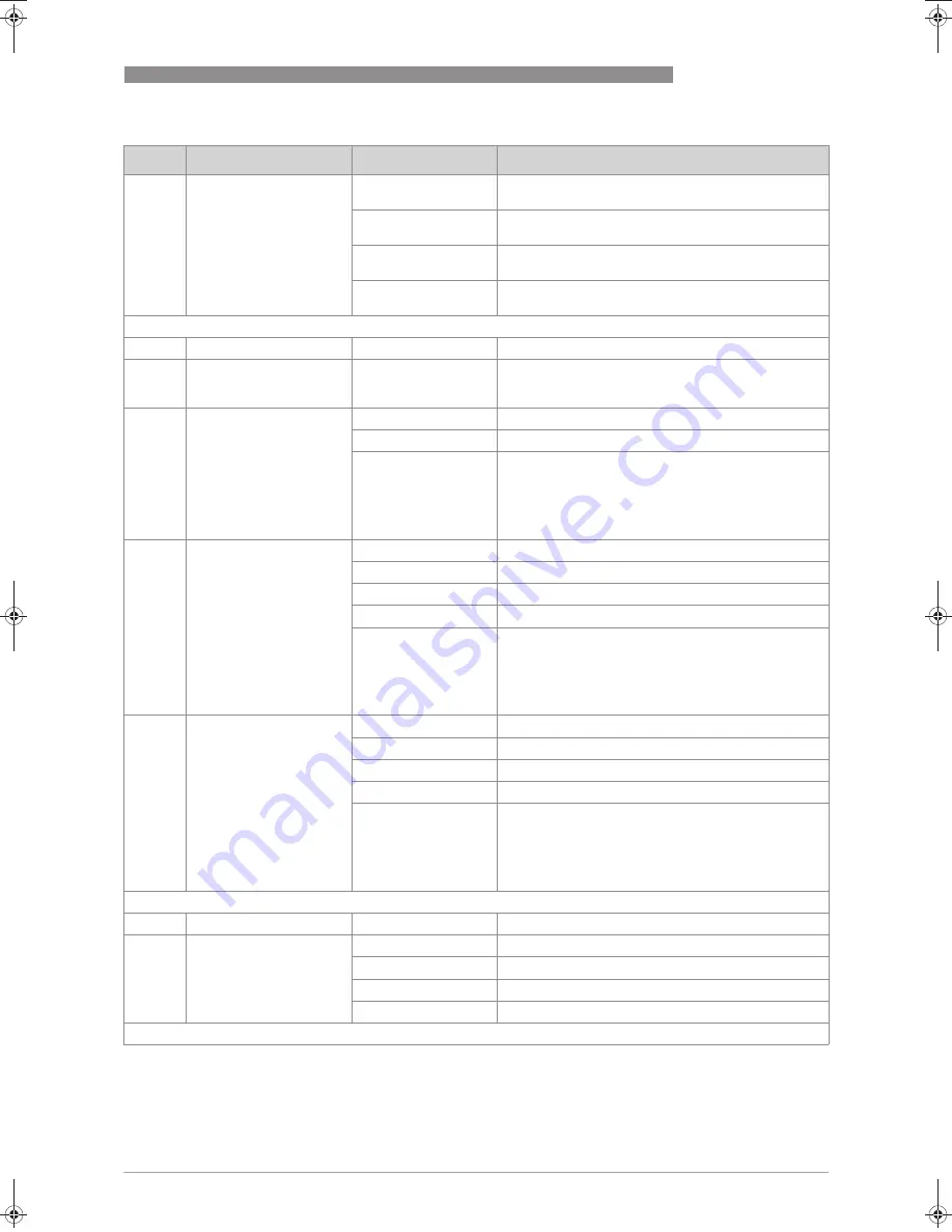
3.3

HART settings

3.3.1

Poll. Addr..

000

 15   

→↑

...

→↑

...

^

Enter HART polling address for "Multidrop mode"

3.3.2

HART SV

HART secondary variable

Total Flow 

...

FAD 

...

^

#available if Meter 

Type = FAD meter (see 

menu item 5.3.1, 

service personnel 

only)

3.3.3

HART TV

HART tertiary variable

Temp. 

...

Pressure 

...

Density      

...

FAD 

...

^

#available if Meter 

Type = FAD meter (see 

menu item 5.3.1, 

service personnel 

only)

3.3.4

HART 4V

HART quaternary variable

Temp. 

..

Pressure 

...

Density      

...

FAD 

...

^

#available if Meter 

Type = FAD meter (see 

menu item 5.3.1, 

service personnel 

only)

3.4

Set fluid and medium

3.4.1

Fluid 

1

Set fluid type

Gas 

...

Gas

Gas Mix. 

...

Gas mixture

Wet Gas 

...

^

Wet gas

1

 When changing fluid: check density

Level

Designation

Selection / entry

Explanation

MA_Siemens_Sitrans_FX300_R02_en_PRT.book  Page 59  Monday, June 22, 2009  8:17 AM

Summary of Contents for SITRANS FX300

Page 1: ......

Page 2: ...d to reproduce this documentation or any part thereof without the prior written authorisation of Siemens Subject to change without notice 2 SI www siemens com flow 06 2009 SFIDK PS 050 F2 02 A5E02100423 Copyright 2009 by Siemens IMPRINT ...

Page 3: ... 12 2 2 3 Device description 13 2 2 4 Free air delivery measurement FAD optional 13 2 2 5 Gross heat meter 14 2 2 6 Dual seal 15 2 3 Nameplate 16 3 Installation 17 3 1 Notes on installation 17 3 2 Storage 17 3 3 Transport 17 3 4 Installation condtitions 18 3 4 1 Measurement of liquids 19 3 4 2 Measurement of vapours and gases 21 3 4 3 Pipelines with control valve 22 3 4 4 Preferred mounting positi...

Page 4: ...tructure 41 6 2 4 Changing the settings in the menu 41 6 2 5 Changing units 42 6 2 6 Measures in the event of faulty indications 43 6 3 Overview of the most important functions and units 44 6 4 Error messages 46 6 5 Menu structure 47 6 5 1 Overview of firmware versions 47 6 5 2 Entering values in change mode 48 6 5 3 Character selection in change mode 48 6 5 4 Menu item Quick Setup 49 6 5 5 Menu i...

Page 5: ...06 2009 SFIDK PS 050 F2 02 A5E02100423 SITRANS FX300 8 Technical data 66 8 1 Functional principle 66 8 2 Technical data 67 8 3 Dimensions and weights 70 8 3 1 Flange versions 70 8 3 2 Sandwich version 73 8 4 Flow tables 75 9 Notes 79 ...

Page 6: ...alled Suitable measures must be taken to avoid water cavitation if it is a possible risk The sensors are made from Stainless Steel 316 L 1 4404 or Hastelloy C22 In your project planning please observe the data given in the corrosion tables The pressure bearing parts have been designed and rated for stationary operation taking into account the maximum pressure and temperature External forces and mo...

Page 7: ...statutory requirements of the following EC directives Pressure Equipment Directive 97 23 EC Low Voltage Directive 73 23 EEC EMC Directive 89 336 EC as well as EN 61010 EMC specification acc to EN 61326 A1 NAMUR recommendations NE 21 and NE 43 The manufacturer certifies successful testing of the product by applying the CE marking CE marking ...

Page 8: ...n over the Internet e g when communicating by e mail may involve gaps in security It is not possible to protect such data completely against access by third parties We hereby expressly prohibit the use of the contact data published as part of our duty to publish an imprint for the purpose of sending us any advertising or informational materials that we have not expressly requested 1 3 2 Disclaimer...

Page 9: ...ation To prevent any injury to the user or damage to the device it is essential that you read the information in this document and observe applicable national standards safety requirements and accident prevention regulations If this document is not in your native language and if you have any problems understanding the text we advise you to contact your local office for assistance The manufacturer ...

Page 10: ...se warnings must be observed without fail Even partial disregard of this warning can lead to serious health problems and even death There is also the risk of seriously damaging the device or parts of the operator s plant WARNING Disregarding this safety warning even if only in part poses the risk of serious health problems There is also the risk of damaging the device or parts of the operator s pl...

Page 11: ...ressure sensor INFORMATION Inspect the cartons carefully for damage or signs of rough handling Report damage to the carrier and to the local office of the manufacturer INFORMATION Check the packing list to check if you received completely all that you ordered INFORMATION Look at the device nameplate to ensure that the device is delivered according to your order Check for the correct supply voltage...

Page 12: ...ch version features 2 centring rings to aid with installation Figure 2 2 Flanged devices with display 1 Version with temperature sensor 2 Version with temperature sensor and optional pressure sensor 3 Version with temperature sensor optional pressure sensor and shut off valve Figure 2 3 Sandwich versions with display 1 Version with temperature sensor 2 Version with temperature sensor and optional ...

Page 13: ...ng can take place with an accuracy of 1 The vortex flowmeter with the optional FAD function can measure the free air delivery online humidity and speed compensated regardless of its function as standard flowmeter The integrated software evaluates the free air delivery automatically online The menu driven user friendly software prompts the operator to enter the pressure relative humidity the requir...

Page 14: ...s the enthalpy of steam changes with the temperature it cannot be assumed to be constant The vortex flowmeter has a special feature which calculates the flow of steam and water as power The enthalpy tables are permanently programmed into the memory of the device The online density compensated mass flow is multiplied by the correct enthalpy to obtain the flow as power output Power QH mass flow Qm x...

Page 15: ...truction material is always the same as the Flow tube itself e g Stainless steel 316L or Hastelloy C22 Chemicals used for the process going through the Flow tube must be compatible with the designated material By using the membrane vent as annunciation valve all requirements for a dual seal device in accordance to above mentioned standard are fulfilled It protects the electronic compartment agains...

Page 16: ...ted on the nameplate Figure 2 5 Example for nameplate 1 Device type 2 Manufacturer 3 Notified ATEX DGRL bodies only available if this option was ordered 4 Connection data nominal diameter and pressure rating 5 PED data 6 Ex data only available if this option was ordered 7 Electrical connection data 8 Manufacturer s website Figure 2 6 Example for nameplate 1 Serial number 2 Order number 3 Type code...

Page 17: ... pressure sensor Do not use lifting chains as they may damage the housing INFORMATION Inspect the cartons carefully for damage or signs of rough handling Report damage to the carrier and to the local office of the manufacturer INFORMATION Check the packing list to check if you received completely all that you ordered INFORMATION Look at the device nameplate to ensure that the device is delivered a...

Page 18: ...he piping the following points must be observed Nominal diameter of connection pipe flange nominal flange diameter of pipe Use flanges with smooth holes e g welding neck flanges Align carefully the holes of the connecting flange and the flowmeter flange Check the compatibility of the gasket material with the process product Make sure that the gaskets are arranged concentrically The flange gaskets ...

Page 19: ...hibited installation Figure 3 2 Upper pipe bend CAUTION Prohibited Installing the device in an upper pipe bend 1 because there is a risk of gas bubbles 2 forming Gas bubbles can lead to pressure surges and inaccurate measurement Figure 3 3 Downpipe and outlet CAUTION Prohibited Installing the device in a downstream pipe 3 or upstream pipe of a outlet 4 There is the risk of partially filled pipes ...

Page 20: ...f liquids CAUTION It is absolutely necessary to comply with the required inlet and outlet runs 1 If the device is installed in a downpipe a standpipe must be installed immediately after it 2 Installing the device in an inclined standpipe 3 Installing the device in a vertical standpipe 4 Installing the device in the lower pipe bend 1 Above a horizontal pipe 2 On a vertical pipe INFORMATION Dependin...

Page 21: ... installation 1 Lower pipe bends 2 Condensate DANGER Prohibited Installing the device in a lower pipe bend 1 because there is a risk of condensate forming 2 Condensate can lead to cavitation and inaccurate measurement Under certain circumstances the device can be destroyed and the measured product can leak CAUTION It is absolutely necessary to maintain the required inlet and outlet runs 1 Inlet an...

Page 22: ...rol valve 1 Recommended installing the device upstream upstream upstream upstream from the control valve at a distance of 5 DN 2 Not recommended Installing the flowmeter directly downstream directly downstream directly downstream directly downstream of control valves due to vortex formation Preferred mounting position 1 Above a horizontal pipe 2 underneath a horizontal pipe not permitted with line...

Page 23: ...ousing Lift the connection housing and turn it to the required position in 90 steps Screw the connection housing back on DANGER All work on the device electrics may only be carried out by appropriately trained personnel The regional occupational health and safety directives must always be observed CAUTION Do not damage the electrical cable by overtwisting it Do not remove the electrical connector ...

Page 24: ...chor fitting and turn it to the required position 3 Press the display onto the spacer pins 4 until it clicks Turn the cover with gasket 5 back onto the housing and tighten it by hand DANGER All work on the device electrics may only be carried out by appropriately trained personnel The regional occupational health and safety directives must always be observed INFORMATION If the measuring device is ...

Page 25: ...o the maximum height 1 shown below up to the connecting screws of the measuring sensor Figure 3 7 Heat insulation on connection piece and signal cable 1 Max height of insulation up to intermediate piece between measuring sensor and signal converter 2 Max thickness of the insulation up to the bend of the pressure pipe 3 Insulation CAUTION The heat insulation 3 may only extend as far as the bend of ...

Page 26: ...423 3 5 Inlet and outlet runs 3 5 1 Minimum inlet runs 1 General inlet run without disturbing flow 20 DN 2 Behind a control valve 50 DN 3 After a pipe diameter reduction 20 DN 1 After a single bend 90 20 DN 2 After a double bend 2x90 30 DN 3 After a double three dimensional bend 2x90 40 DN ...

Page 27: ...Upstream of pipe expanders pipe bends control valves etc 5 DN 2 Upstream of metering points 5 6 DN INFORMATION The interior of the pipe at the metering points must be free of burrs and other flow impediments The measuring device has an internal temperature sensor External temperature sensor must be located 5 DN behind the flow sensor outlet Use sensors that are as short as possible to avoid distur...

Page 28: ...ss bolts or bolts and nuts are not included in the scope of delivery Ensure that the measuring flange is concentrically fitted Note the exact installation length of the measuring device when preparing the metering point CAUTION Installation assembly start up and maintenance may only be performed by appropriately trained personnel The regional occupational health and safety directives must always b...

Page 29: ...the gaskets 1 between measuring sensor and flange and align them Check that the gasket is concentric and that it is not protruding into the pipe cross section Install the gasket bolts and fastening nuts on the other side of the flange Align the measuring device and the gaskets so they are concentric Now tighten all nuts bit by bit alternately across the diagonal Figure 3 12 Installing devices in f...

Page 30: ... two flanges Insert the gaskets 6 between measuring sensor 1 and flanges and align them Check that the flange is concentric Install the remaining bolts washers and nuts Do not yet tighten the nuts Turn the centring ring 2 in a counter clockwise direction and align the device Check that the gaskets 6 are concentric they must not protrude into the pipe cross section Now tighten all nuts bit by bit a...

Page 31: ...s for electrical installations DANGER For devices used in hazardous areas additional safety notes apply please refer to the Ex documentation WARNING Observe without fail the local occupational health and safety regulations Any work done on the electrical components of the measuring device may only be carried out by properly trained specialists INFORMATION Look at the device nameplate to ensure tha...

Page 32: ...o facilitate installation the connection plug can be removed from the device The plug is configured in such a way as to prevent reverse polarity Connect the grounding to terminal 7 alternatively use the PE terminal on the connection piece between measuring sensor and signal converter 8 Tighten the cable glands Hand tight the housing cover with gasket Figure 4 1 Signal converter housing with housin...

Page 33: ...se output Pulse output When using the pulse output two separate signal circuits are necessary if the pulse output is utilized together with analogue signals Each signal circuit requires its own power supply The total resistance must be adapted so that the total current Itot does not exceed 100 mA Connection current output on terminals A A Connection pulse output on terminals B B The maximum load r...

Page 34: ...e unit and the conversion factor can be changed in menu item 3 2 8 Conf Tot User specific units User Def can also be entered but the conversion factor must always be entered based on the base unit For a sample calculation see chapter 6 2 5 Change units The maximum frequency of the pulse output is 0 5 Hz INFORMATION The supply voltage has to be between 14 VDC and 36 VDC This is based on the total r...

Page 35: ...pulse output is fmax 0 5 Hz The maximum frequency of the pulse output is fmax 0 5 Hz Jumper in NAMUR setting Jumper in NAMUR setting Jumper in NAMUR setting Jumper in NAMUR setting Ri 900 Ω Umax 36 VDC Jumper in high current setting Jumper in high current setting Jumper in high current setting Jumper in high current setting Open Maximum voltage Umax 36 VDC Closed current IR 1 mA Closed Maximum cur...

Page 36: ...Both of these electrical connections are equally effective from a technical point of view Figure 4 5 Grounding connection 1 Electrical grounding connection on connection piece between measuring sensor and signal converter 2 Electrical grounding connection on housing DANGER The measuring device has to be grounded properly to achieve accurate measurement The grounding wire may not transfer any inter...

Page 37: ...bles used must be undamaged and must comply with regulations The cables must be laid with a loop 1 upstream of the measuring device to prevent water from getting into the housing The cable feedthroughs 2 must be tightened Align the measuring device so that the cable feedthrough is never facing up 3 Close the unused cable feedthroughs using blind plugs 4 Do not remove the required cable bushing fro...

Page 38: ...Revision The device performs a self test and switches to measurement mode Here all of the parameters preset for the customer are analysed and checked for plausibility and the current measured value is displayed 5 2 Start up and control INFORMATION The flowmeter is largely maintenance free Observe the application limits in respect of temperature and medium Additional information refer to Technical ...

Page 39: ...s used CAUTION The switching point of the magnetic sensors is directly under the glass panel above the appropriate symbol Only touch the symbol vertically and from the front using the bar magnet Touching it from the side may cause a malfunction Figure 6 1 Display and operating elements 1 Enter button bar magnet 2 Right button bar magnet 3 Up button bar magnet 4 Up button mechanical 5 Enter button ...

Page 40: ...change mode In change mode Move the input cursor one position to the right after the last digit the input cursor jumps back to the beginning In measuring mode In measuring mode In measuring mode In measuring mode Switch between measured values and error messages Change between the menu items within a menu level In change mode In change mode In change mode In change mode Changing parameters and set...

Page 41: ... in the selected menu i The current values or settings are displayed Use the and keys to change the value or setting Save the new value or setting using the key Some menu items contain several setting options They are displayed in sequence by pressing the key i Takes you back to the main menu Press the key to save the settings i The query Save Yes appears Switch between Yes and No by pressing the ...

Page 42: ...flow measurement The flow units can be changed in menu item 1 1 4 Max Flow User defined units can be entered using User Def The unit text as well as the conversion factor number can be entered here The conversion factor must always be entered based on the base unit Conversion Menu items Procedure Display Procedure Display 107 2 m3 h 5 0000600 00 L min 1 3 x 3 x 3 x 3 x 1 1 1 1 1 1 Language 6 Displ...

Page 43: ... of the whole number value of the internal totalizer Max pulses per hour Example Menu items 6 2 6 Measures in the event of faulty indications If the indications on the display or the responses to keypad commands are faulty you have to do a hardware reset Switch the power supply OFF and ON again fmax 0 5 Hz 1 pulse break 2 seconds Max pulses hour 1800 1800 1800 1800 pulses Flow Qmax Factor A1 Coef ...

Page 44: ...e 4 mA value of the current output 1 1 6 Timeconst Time constant damping value s 2 1 1 Test I Check current output 2 1 2 Test P Test pulse output 3 1 1 Error Msg Error indicator Yes error messages are displayed No error messages are suppressed A flashing cursor at the top left indicates that error messages are present Table 6 4 The most important functions Volume Standard volume Mass Liquids steam...

Page 45: ... volume Mass Liquids steams gases Gas Liquids steams gases m3 L ft3 h ft3 gal ImpGal cm3 dm3 bbl User Def m3 norm L norm ft3 std User Def kg t lb g User Def Table 6 6 Totalizer units Temp Absolute pressure over Power Energy Density C F K User Def Pa g kPa g MPa g kg ms2 g kp cm2 g atm g torr g bar g mbar g psi g lbf ft2 g kgf cm2 g inHg g mmHg g mmH2O g User Def kJ h MJ h GJ h Btu h th kcal h User...

Page 46: ...onfiguration Contact service if error message persists Amp Fail Error in the pre amplifier stage Contact service Chk Instal Quality of the vortex signal too poor 1 Check qmin 2 Excessive pipe vibration and faulty flow profile Low Signal Amplitude of vortex signal is too low 1 qmin ok 2 If qmin OK contact service Hi Signal Amplitude of vortex signal is too high Occurs with media of high density 1 C...

Page 47: ...ollowing table contains an overview of all menu items in the first menu level For a complete description of the menu note the firmware version of your measuring device and follow the relevant instructions in the table Menu items Firmware version Basic Firmware version Steam Firmware version Gas 1 Quick setup refer to Menu item Quick Setup on page 49 2 Tests refer to Menu item Tests on page 50 3 Se...

Page 48: ...the beginning Cycles through available values and characters moves the decimal point to the right Accepting the entry 6 5 3 Character selection in change mode Depending on the menu function you can choose from the following characters Numbers Lowercase letters Uppercase letters Special characters 0 1 2 3 4 5 6 7 8 9 a b c d e f g h i j k l m n o p q r s t u v w x y z A B C D E F G H I J K L M N O ...

Page 49: ...splay Unit Display Max Flow Display flow rate in units in of maximum flow rate 3 m3 h norm Unit Select unit for standard volume flow measurement 00600 0000 or other value m3 h norm Enter value for the maximum standard volume flow rate Display Unit Display Max Flow Display flow rate in units in of maximum flow rate 4 kg h Unit Select unit for mass flow measurement 00600 0000 or other value kg h Ent...

Page 50: ...alue The following is then displayed Contin Yes Contin Yes Contin Yes Contin Yes continue with the test of current output function Contin No Contin No Contin No Contin No back to menu The test current is maintained until the menu has been exited Level Designation Selection entry Explanation 2 1 1 Test I 4 mA Test current output 8 mA 12 mA 16 mA 20 mA 2 1 2 Test P 0 5003 Hz Test pulse output Table ...

Page 51: ...rrent 4 20mA Current output 4 20 mA 4 20 22E Current output 4 20 mA or error current 22 mA 4 20 3 55E Current output 4 20 mA or error current 3 55 mA 3 2 5 Function P Pulse output Yes Activate pulse output No Deactivate pulse output 3 2 7 Totalizer Totalizer Tot on Start totalizer Tot off Stop totalizer value is held 3 2 8 Tot Conf Configure totalizer available if Maes Inst Volume see menu item 1 ...

Page 52: ...id and medium 3 4 1 Fluid 1 Set fluid type Gas Gas Liquid Liquid Steam Steam 3 4 2 Medium Set medium available if Fluid Gas or Liquid see menu item 3 4 1 Custom Customer medium available if Fluid Steam see menu item 3 4 1 Sat Steam Saturated steam Custom 1 Density check 3 5 Set pressure temperature and density 3 5 1 T sensor Internal temperature sensor No No temperature sensor available Yes Temper...

Page 53: ...temperature kg m3 Unit Set density unit 00000 0000 kg m3 1 Operating density 3 5 9 Dens Norm 2 00000 0000 kg m3 Enter density for reference conditions pressure and temperature 3 6 3 6 1 Remote 0 000 length m max 30m 3 6 2 Cable Coef 14 074 Cable Coef 1 Disp off Disp on 2 available if Maes Inst Norm Vol Level Designation Selection entry Explanation ...

Page 54: ...r error current 22 mA 4 20 3 55E Current output 4 20 mA or error current 3 55 mA 3 2 2 Variable I available if Meter Type Gross Heat see menu item 5 4 1 service menu Set output variable for current output Maes Inst Flow rate Power Power 3 2 3 Power Unit available if Meter Type Gross Heat see menu item 5 4 1 service menu Set unit for heat output kJ h Unit Select unit for measuring heat output Disp ...

Page 55: ...it for mass flow measurement 0000000000 kg Enter preset totalizer value Reset Yes Reset No Do not reset totalizer Reset totalizer Disp off Disp on Do not display totalizer Display totalizer 3 2 9 E tot on available if Meter Type Gross Heat see menu item 5 4 1 service menu Energy totalizer Tot on Start totalizer Tot off Stop totalizer value is held 3 2 10 Energ Unit available if Meter Type Gross He...

Page 56: ...ble 3 5 2 P sensor Pressure sensor Intern Internal pressure sensor No pressure sensor available 3 5 3 Sat P T available if Medium Sat Steam see menu item 3 4 2 Density calculation for saturated steam Sat Temp Density calculation for saturated steam from saturated temperature Sat Pres Density calculation for saturated steam from saturated pressure 3 5 4 Temp Opr for saturated steam with Sat Temp or...

Page 57: ...item 3 5 2 0005 00000 V Exciting voltage of pressure sensor 3 5 11 P Sen P1V1 available if P Sensor Internal see menu item 3 5 2 Pressure sensor Enter 1st calibration point 0001 00000 P1 kg cm2g 0002 00000 V1 mV 3 5 12 P Sen P2V2 available if P Sensor Internal see menu item 3 5 2 Pressure sensor Enter 2nd calibration point 0005 00000 P2 kg cm2g 0048 00048 V2 mV 3 6 3 6 1 Remote 0 000 length m max ...

Page 58: ...urrent 4 20mA Current output 4 20 mA 4 20 22E Current output 4 20 mA or error current 22 mA 4 20 3 55E Current output 4 20 mA or error current 3 55 mA 3 2 5 Function P Pulse output Yes Activate pulse output No Deactivate pulse output 3 2 7 Totalizer Totalizer Tot on Start totalizer Tot off Stop totalizer value is held 3 2 8 Tot Conf Configure totalizer available if Maes Inst Volume see menu item 1...

Page 59: ...address for Multidrop mode 3 3 2 HART SV HART secondary variable Total Flow FAD available if Meter Type FAD meter see menu item 5 3 1 service personnel only 3 3 3 HART TV HART tertiary variable Temp Pressure Density FAD available if Meter Type FAD meter see menu item 5 3 1 service personnel only 3 3 4 HART 4V HART quaternary variable Temp Pressure Density FAD available if Meter Type FAD meter see ...

Page 60: ...er temperature value 3 4 8 Atm Press available if Meter Type FAD meter see menu item 5 4 1 service personnel only Atmospheric pressure Pa Unit Select pressure unit 00001 0000 Pa Enter pressure value 3 4 9 Fil P Drop available if Meter Type FAD meter see menu item 5 4 1 service personnel only Pressure drop via filter at compressor inlet Pa Unit Select pressure unit 00000 0000 Pa Enter pressure valu...

Page 61: ... Density at operating pressure and operating temperature kg m3 Unit Set density unit 00011 0000 kg m3 Operating density 3 5 7 Temp Norm available if Maes Inst Norm Vol see menu item 1 1 3 00000020 0 C Enter normal temperature Unit as 3 5 4 3 5 8 Pres Norm available if Maes Inst Norm Vol see menu item 1 1 3 00000000 0 Pa Enter normal pressure Unit as 3 5 5 3 5 9 Dens norm for unknown gases using st...

Page 62: ...A5E02100423 3 5 12 P Sen P2V2 available if P Sensor Internal see menu item 3 5 2 Pressure sensor 2nd calibration point 0005 00000 P2 kg cm2g 0048 00048 V2 mV 3 6 3 6 1 Remote 0 000 length m max 30m 3 6 2 Cable coeff 14 074 Cable Coef Level Designation Selection entry Explanation ...

Page 63: ...ch off the power supply Unscrew the front cover Detach the display from the spacer pins Detach the display cable 1 Detach the measuring sensor cable 3 Loosen the three fixing screws 5 Phillips Pull out signal converter Insert new signal converter Tighten the three screws Attach measuring sensor cable 3 Caution ensure that the measuring sensor cables are not on top of the spacer pins 4 May be damag...

Page 64: ...it will rarely present any problems INFORMATION For more precise information please contact your local representative CAUTION Should you nevertheless need to return a device for inspection or repair please pay strict attention to the following points Due to statutory regulations on environmental protection and safeguarding the health and safety of our personnel manufacturer may only handle test an...

Page 65: ...no or serial no The device has been operated with the following medium This medium is water hazardous toxic caustic flammable We checked that all cavities in the device are free from such substances We have flushed out and neutralized all cavities in the device We hereby confirm that there is no risk to persons or the environment through any residual media contained in the device when it is return...

Page 66: ...he Karman vortex street The measuring tube contains a bluff body behind which vortex shedding occurs The frequency f f f f of the vortex shedding is proportional to the flow rate v v v v The nondimensional Strouhal number S S S S describes the relationship between vortex frequency f f f f width b b b b of bluff body and the mean flow velocity v v v v The vortex frequency is recorded at the sensor ...

Page 67: ...ensor Standard Basic device in flange version with integrated temperature measurement Basic device in sandwich version with integrated temperature measurement Optional Basic device with additional pressure measurement Basic device with additional pressure measurement and shut off valve for pressure sensor Dual measuring device in both flange and sandwich version redundant measurement Dual measurin...

Page 68: ...ms 2 0 80 m s 6 6 262 5 ft s DN15 3 0 45 m s 9 8 148 ft s DN25 2 0 70 m s 6 6 230 ft s For detailed information see chapter Flow tables Other conditions Other conditions Other conditions Other conditions Protection category IP 66 67 Installation conditions Inlet run 20 x DN without disturbing flow after pipe narrowing after a single 90 bend 30 x DN after a double bend 2x90 40 x DN after a double t...

Page 69: ...t Current output Current output Current output Description of the used abbreviations Uext external voltage RL load resistance Measuring range 4 20 mA max 20 8 mA HART protocol Load Minimum 0 Ω maximum RL Uext 14 VDC 22 mA Error signal Acc to NAMUR NE43 Upper value 21 0 mA Lower value 3 6 mA not with HART protocol Pulse output Pulse output Pulse output Pulse output Pulse rate Max 0 5 pulse s corres...

Page 70: ... 17 3 105 200 265 174 3 7 1 6 5 25 40 28 5 115 200 265 174 3 7 9 7 3 25 100 28 5 140 200 265 174 3 9 9 9 3 40 40 43 1 150 200 270 174 5 10 8 10 2 40 100 42 5 170 200 270 174 5 14 8 14 2 50 16 54 5 165 200 275 174 5 12 7 12 1 50 40 54 5 165 200 275 174 5 12 9 12 3 50 63 54 5 180 200 275 174 5 16 9 16 3 50 100 53 9 195 200 275 174 5 18 4 17 8 80 16 82 5 200 200 290 174 25 17 4 16 8 80 40 82 5 200 20...

Page 71: ...7 8 200 16 206 5 340 300 350 208 5 38 4 37 8 200 25 206 5 360 300 350 208 5 47 4 46 8 200 40 206 5 375 300 350 208 5 55 4 54 8 250 10 260 4 395 380 370 236 5 58 0 57 4 250 16 260 4 405 380 370 236 5 59 0 58 4 250 25 258 8 425 380 370 236 5 75 0 74 4 250 40 258 8 450 380 370 236 5 93 0 92 4 300 10 309 7 445 450 395 261 76 3 75 7 300 16 309 7 460 450 395 261 82 8 82 2 300 25 307 9 485 450 395 261 99...

Page 72: ...6 9 13 28 7 12 4 27 4 2 600 49 3 1 9 165 6 5 200 7 9 275 10 8 174 3 6 9 14 5 32 0 13 9 30 6 3 150 78 3 1 190 7 5 200 7 9 290 11 4 174 5 6 9 20 4 45 0 19 8 43 7 3 300 78 3 1 210 8 3 200 7 9 290 11 4 174 5 6 9 23 4 51 6 22 8 50 2 3 600 73 7 2 9 210 8 3 200 7 9 290 11 4 174 5 6 9 24 4 52 8 23 8 52 5 4 150 102 4 4 0 230 9 1 250 9 8 310 12 2 176 5 7 0 24 52 9 23 4 51 6 4 300 102 4 4 0 255 10 0 250 9 8 ...

Page 73: ... 4 13 c 179 mm 7 05 Dimension H x 2 Specified weight 2 80 kg Size Pressure rating Dimensions mm Weight kg DN PN d D L H l With Without pressure sensor 15 100 16 45 65 265 174 25 4 1 3 5 25 100 24 65 65 265 174 25 4 9 4 3 40 100 38 82 65 270 174 5 5 5 4 9 50 100 50 102 65 275 174 5 6 6 6 80 100 74 135 65 290 174 25 8 8 8 2 100 100 97 158 65 310 176 5 10 1 9 5 ...

Page 74: ...0 8 9 48 1 300 0 94 2 56 2 56 10 43 6 82 10 8 9 48 1 600 0 94 2 56 2 56 10 43 6 82 10 8 9 48 1 150 1 5 3 23 2 56 10 63 6 87 12 13 10 8 1 300 1 5 3 23 2 56 10 63 6 87 12 13 10 8 1 600 1 5 3 23 2 56 10 63 6 87 12 13 10 8 2 150 1 97 4 02 2 56 10 83 6 87 14 55 13 23 2 300 1 97 4 02 2 56 10 83 6 87 14 55 13 23 2 600 1 97 4 02 2 56 10 83 6 87 14 55 13 23 3 150 2 91 5 31 2 56 11 42 6 82 19 4 18 08 3 300 ...

Page 75: ...2 150 6 30 13 421 86 7960 111445 200 8 52 66 792 42 13911 209335 250 10 90 5 1266 8 23908 334653 300 12 113 41 1839 8 29960 486024 Values based on water at 20 C 68 F Air 15 6 79 32 56 1794 8602 25 1 10 20 114 0 2695 30116 40 1 25 35 326 63 6697 86287 50 2 43 89 565 49 11595 149388 80 3 96 14 1238 60 25398 327207 100 4 165 19 2128 27 43639 562236 150 6 374 23 4821 57 98862 1273738 200 8 702 95 9056...

Page 76: ... 2 7x 998 ρ 0 47 1 23x 998 ρ 0 47 2 Gas steam DN15 300 12 6x 1 29 ρ 0 5 3 16 4x 1 29 ρ 0 5 4 7x 998 ρ 0 47 3 23x 998 ρ 0 47 4 ρ operating density kg m3 1 Minimum flow rate 0 3 m s maximum flow rate 7 m s 2 Minimum flow rate 0 984 ft s maximum flow rate 23 ft s 3 Minimum flow rate 2 m s maximum flow rate 80 m s DN15 up to 45 m s and DN25 up to 70 m s 4 Minimum flow rate 6 6 ft s maximum flow rate 2...

Page 77: ...093 200 8 821 91 10279 1201 6 21970 1396 5 29675 1574 9 37743 250 10 1313 9 16433 1920 9 35122 2232 5 47439 2517 7 60337 300 12 1908 3 23866 2789 8 51010 3242 4 68899 3656 6 87630 Overpressure bar 10 5 14 17 5 20 Density kg m 5 88803 7 60297 9 31702 10 5442 Temperature C 186 2 198 5 208 5 215 Flow rate min max min max min max min max DN EN 1092 1 NPS ASME B16 5 kg h kg h kg h kg h kg h 15 12 78 19...

Page 78: ...35 2 43703 200 8 1824 8 23004 2632 1 47859 3069 1 65072 3447 2 82092 250 10 2917 2 36774 4207 7 76508 4906 4 104030 5510 8 131230 300 12 4236 8 53410 6111 1 111120 7125 8 151080 8003 6 190600 Overpressure psig 150 200 250 300 Density lbs ft 0 3627 0 4681 0 5735 0 6792 Temperature F 366 08 388 04 406 22 422 06 Flow rate min max min max min max min max DN EN 1092 1 NPS ASME B16 5 lbs h lbs h lbs h l...

Page 79: ...NOTES 9 79 SITRANS FX300 www siemens com flow 06 2009 SFIDK PS 050 F2 02 A5E02100423 ...

Page 80: ......

Reviews: