Bay Unit
19
7SS52 V4 Manual
C53000-G1176-C182-3
2.2.2
Modules and Submodules
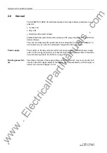
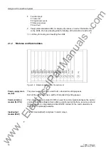
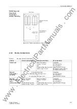
Figure 2-4 Module arrangement in the bay unit 7SS523
PFE module
In the PFE module the firmware is located and processed; it also contains the current
transformers and the measured value acquisition function.
SAF module
The SAF module contains the power supply and the alarm and trip relays.
EFE module
The EFE contains the binary inputs and receives indications (e.g. from isolators and
circuit breakers).
Heavy-duty
current terminals
The heavy-duty current terminals automatically short-circuit the current transformer
when the module is withdrawn.
Plug-in modules
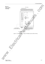
The plug-in modules are identified according to their position in a coordinate system.
The connections inside a module are numbered consecutively from left to right
(viewed from the rear), see example in Figure 2-8, page 24.
8
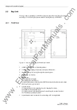
LED key for testing and resetting the LEDs and for display of operational
measured values in 4-line mode
9
Freely parameterizable LEDs for display of process or device information. Next
to the LEDs, there is a labeling strip for labeling of the function of each LED.
10 Freely parameterizable LED.
www
. ElectricalPartManuals
. com

