Connection Method
27
7SS52 V4 Manual
C53000-G1176-C182-3
2.3.2.3
D-SUB Female Connectors
Connectors
The serial ports of the central unit and of the bay units have 9-pole D-SUB female con-
nectors. The serial ports include:
•
the PC port at the front of the central unit and the bay unit
•
the service port at the back of the central unit
•
the system port at the back of the central unit
•
the clock synchronization interface at the back of the central unit
For assignment of the connectors, please refer to the Figures A-3, page 342 and A-5,
page 345 in the Appendix.
Connection method
You can use any standard 9-pole D-SUB plug connectors per MIL-C-24308 and
DIN 41652.
Depending on the device version, the pin assignment is the same as for an RS232 or
RS485 port.
You can use for connection e.g. a 5-strand, shielded interface cable.
Tools
No tools are required for connection the interface cables.
2.3.2.4
Fiber-Optic Cable Connections
Central unit
Depending on the variant ordered, the service and the system port on the rear of the
central unit may have additional fiber-optic connections (Figure 2-6, page 22).
Moreover, the central unit is connected with the bay units by fiber-optic cables. The
bay unit connectors are located on the back of the central unit (Figure 2-6, page 22).
Bay units
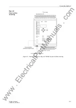
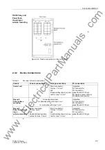
Depending on the mounting variant, the fiber-optic interface to the central unit is locat-
ed on the bottom (Figure 2-7, page 23) or the rear (Figure 2-8, page 24) of the bay
unit. For assignment of the connectors, please refer to Figure A-4, page 343 in the Ap-
pendix.
Connection method
FO connector type:
ST connector
Use fiber type:
Multimode FO,
G50/125 µm,
G62.5/125 µm,
G100/140 µm
for wave length:
λ
approx. 820 nm
www
. ElectricalPartManuals
. com


