Fault Analysis
297
7SS52 V4 Manual
C53000-G1176-C182-3
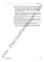
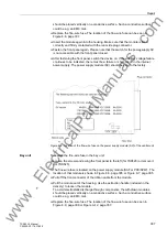
Double-click in the navigation window of the DIGSI Device Configuration the folder
Online
. This will open the directory containing the operating functions of the device
(see Figure 6-1, page 213).
Click
Parameters
. The function selection now shows the groups of parameters.
Double-click
Parametergruppe
. You will now see the “Parameter Group” window.
Double-click the function
Schutz allgemein
. You will now see the “Schutz
allgemein – Parametergruppe A” window.
Check the checkbox
Weitere Parameter anzeigen
.
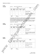
In parameter
(
), click the column
Wert
.
You will now see a list of setting options.
Click
On
in the list and then
OK
.
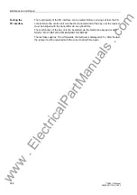
The second way describes how the test mode is activated by the hardware:
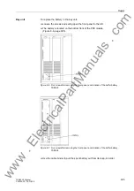
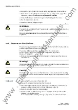
Set jumper X34 on the ZPS-SK module to “on”. For the location of the jumper on
the board, and the jumper settings of the ZPS-SK module, please refer to Chapter
A.4.1, page 348.
Set jumper X34 on the ZPS-SBK module to “on”.
Reset the device by switching the auxiliary voltage off and on again.
Testing the
fiber-optic cables
To further locate the failure, test the affected duplex channel by shorting it with a fiber-
optic cable between the transmitter and the receiver. A short FO cable is included in
the delivery of the central unit.
If the substation is operating and the control voltage for the TRIP circuits is on, an
additional safeguard against spurious tripping must be provided by setting the
marking
TRIP commands blocking
to
on
(see Chapter 6.3.2.1, page 226).
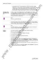
Short the affected duplex channel with a fiber-optic cable between the transmitter
and the receiver. You can short as many duplex channels as you like. If the failure
disappears after installing the fiber-optic cable, the signal path, including the LMZ
converter module, is healthy.
Remove the fiber-optic cable which connects the transmitter and the receiver of the
channel you have just checked.
Reconnect the fiber-optic cables running to the bay unit.
Connect the fiber-optic cables on the bay unit using a fiber-optic coupler. This
coupler is included in the delivery of the central unit. It allows you to check
transmission paths with a length of up to 750 m.
After completion of the test, remove the jumper from the ZPS-SK and ZPS-SBK
module and reestablish the old settings.
If the test of the fiber-optic cables has been successful as well, the cause of the
disturbed channel is very probably a defect on the bay unit.
Try to replace the bay unit by a different one.
www
. ElectricalPartManuals
. com


