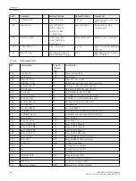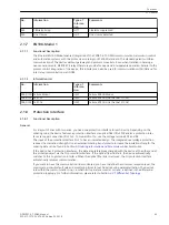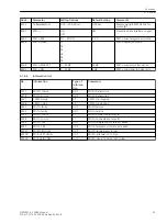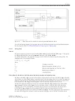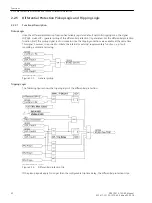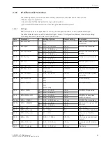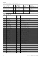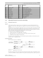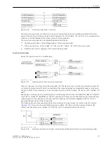
Considering the variations of voltage and frequency, the value set should be at least 2.5 to 3 times higher than
the calculated charging current. Moreover, the pickup value should not be smaller than 15 % of the primary
rated current of the largest transformer in the protection configuration.
If setting is performed from a personal computer using DIGSI, the parameters can be set either as primary or as
secondary quantities. If secondary quantities are set, all currents must be converted to the secondary side of
the current transformers.
Time Delays
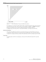
In special application cases, it may be advantageous to delay the tripping of the differential protection using
an additional timer, e.g. in case of reverse interlocking. The time delay
87N L: T-DELAY
(address 1224) is
only started upon detection of an internal fault. This parameter can only be set in DIGSI at Display Additional
Settings.
With the inrush current restraint activated, the time delay
87N L: T-DELAY
must be at least 20 ms for the
blocking by the inrush current restraint to be effective.
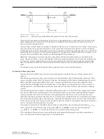
If it is desired that a TRIP command is generated in the event of an internal fault only if simultaneously the
current of the local line end has exceeded a specific quantity, then this current threshold can be set for
enabling the differential protection TRIP at address 1225
87N L: I>RELEAS
. This parameter can only be set
in DIGSI at Display Additional Settings.
Restricted Ground-Fault Protection in Resonant-grounded/Isolated Systems
The ground fault differential protection can be applied in power systems whose starpoint is not grounded or
grounded through an arc suppression coil (Petersen coil). It is based on the power values. This requires the
phase voltages or the 3V0 voltage (Appendix
) to be connected to the
devices at both ends of the protected object.
Funktionsbeschreibung
General
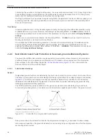
Single-phase ground faults are not detected by the short-circuit protection since no short circuit current flows.
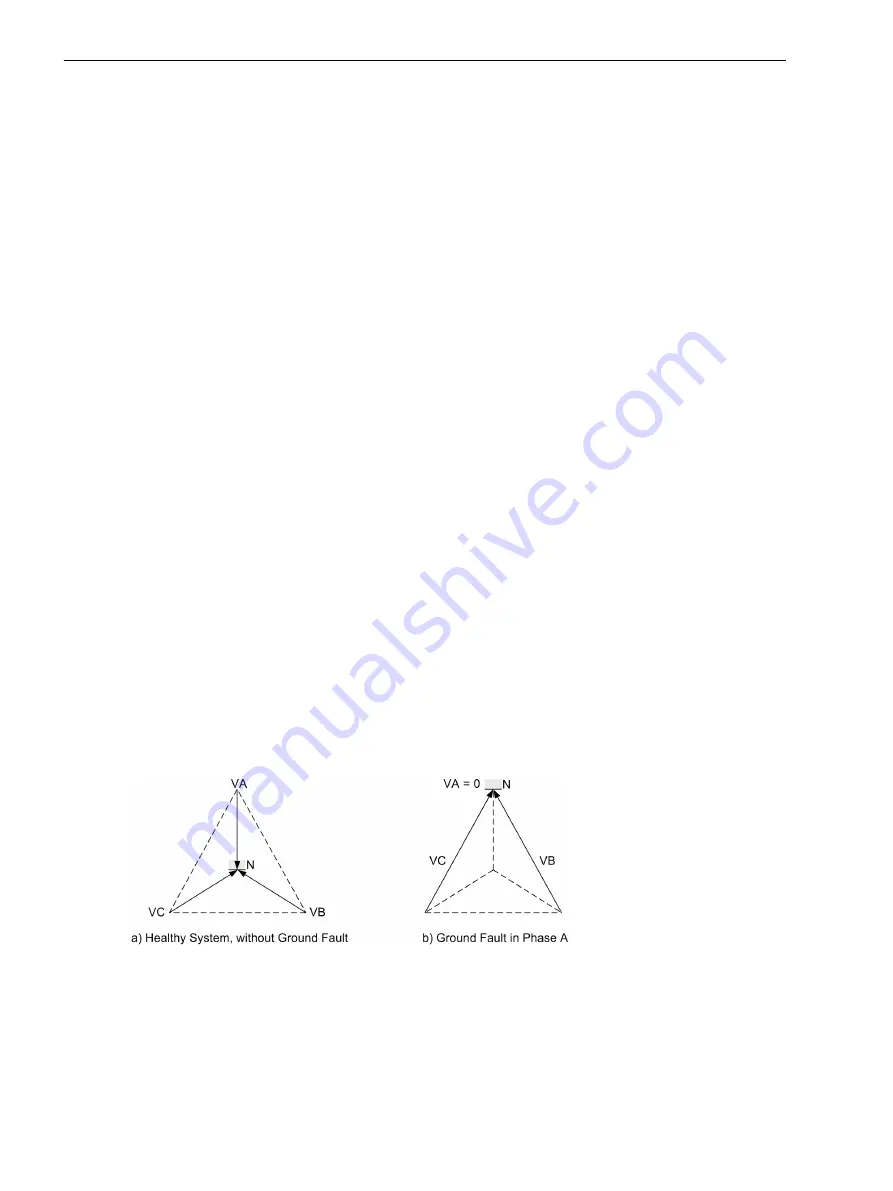
The power system operation is not immediately affected by a ground fault (the voltage triangle is maintained,
). Therefore, fast tripping is usually not required or desired. The ground fault is to be detected,
indicated and the affected piece of equipment is to be localized, if possible, eliminating the ground fault by
initiating appropriate switching operations.
The 7SD80 enables the precise localization of the piece of equipment (line) affected by the ground fault.
In resonant-grounded systems, a core balance current transformer must be used to detect the ground current.
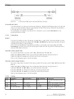
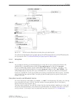
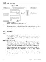
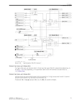
[erdschluss-im-nicht-geerdeten-netz-260702-wlk, 1, en_US]
Figure 2-13
Ground fault in non-grounded neutral system
Pickup
Pickup occurs when the settable threshold for the displacement voltage 3·V
0
is exceeded. To obtain steady-
state measured quantities, the ground fault detection can be delayed by a configurable time after the displace-
ment voltage has occurred.
2.2.4
2.2.4.1
Functions
2.2 Phase Comparison Protection and Ground Differential Protection
58
SIPROTEC 4, 7SD80, Manual
E50417-G1100-C474-A2, Edition 02.2018
Summary of Contents for SIPROTEC 4 7SD80
Page 8: ...8 SIPROTEC 4 7SD80 Manual E50417 G1100 C474 A2 Edition 02 2018 ...
Page 10: ...10 SIPROTEC 4 7SD80 Manual E50417 G1100 C474 A2 Edition 02 2018 ...
Page 18: ...18 SIPROTEC 4 7SD80 Manual E50417 G1100 C474 A2 Edition 02 2018 ...
Page 248: ...248 SIPROTEC 4 7SD80 Manual E50417 G1100 C474 A2 Edition 02 2018 ...
Page 298: ...298 SIPROTEC 4 7SD80 Manual E50417 G1100 C474 A2 Edition 02 2018 ...
Page 312: ...312 SIPROTEC 4 7SD80 Manual E50417 G1100 C474 A2 Edition 02 2018 ...
Page 322: ...322 SIPROTEC 4 7SD80 Manual E50417 G1100 C474 A2 Edition 02 2018 ...
Page 400: ...400 SIPROTEC 4 7SD80 Manual E50417 G1100 C474 A2 Edition 02 2018 ...
Page 402: ...402 SIPROTEC 4 7SD80 Manual E50417 G1100 C474 A2 Edition 02 2018 ...

