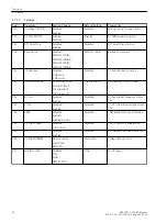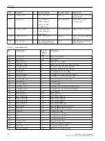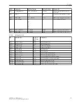
Addr.
Parameter
Setting Options
Default Setting
Comments
206
CT SECONDARY
1A
5A
1A
CT Rated Secondary Current
207
SystemStarpoint
Grounded
Peterson-C.Gnd.
Isolated
Grounded
System Starpoint is
220
I4 transformer
Not connected
In prot. line
In prot. line
I4 current transformer is
221
I4/Iph CT
0.010 .. 5.000
1.000
Matching ratio I4/Iph for CT's
230
Rated Frequency
50 Hz
60 Hz
50 Hz
Rated Frequency
240A
TMin TRIP CMD
0.02 .. 30.00 sec
0.10 sec
Minimum TRIP Command Duration
241A
TMax CLOSE CMD
0.01 .. 30.00 sec
1.00 sec
Maximum Close Command Dura-
tion
242
T-CBtest-dead
0.00 .. 30.00 sec
0.10 sec
Dead Time for CB test-autoreclo-
sure
260
Threshold BI 1
Thresh. BI 176V
Thresh. BI 88V
Thresh. BI 19V
Thresh. BI 176V
Threshold for Binary Input 1
261
Threshold BI 2
Thresh. BI 176V
Thresh. BI 88V
Thresh. BI 19V
Thresh. BI 176V
Threshold for Binary Input 2
262
Threshold BI 3
Thresh. BI 176V
Thresh. BI 88V
Thresh. BI 19V
Thresh. BI 176V
Threshold for Binary Input 3
263
Threshold BI 4
Thresh. BI 176V
Thresh. BI 88V
Thresh. BI 19V
Thresh. BI 176V
Threshold for Binary Input 4
264
Threshold BI 5
Thresh. BI 176V
Thresh. BI 88V
Thresh. BI 19V
Thresh. BI 176V
Threshold for Binary Input 5
265
Threshold BI 6
Thresh. BI 176V
Thresh. BI 88V
Thresh. BI 19V
Thresh. BI 176V
Threshold for Binary Input 6
266
Threshold BI 7
Thresh. BI 176V
Thresh. BI 88V
Thresh. BI 19V
Thresh. BI 176V
Threshold for Binary Input 7
Oscillographic Fault Records
The 7SD80 multifunctional protection with control is equipped with a fault record memory. The instantaneous
values of the measured values
i
A
, i
B
, i
C
, i
E
, i
EE
und v
A
, v
B
, v
C
, 3
Ι
0
diff
, 3
Ι
0
rest
(voltages in accordance with connection) are sampled at intervals of 1.0 ms (for 50 Hz) and stored in a
revolving buffer (20 samples per cycle). In the event of a fault, the data is stored for a set period of time, but
not for more than 5 seconds. Up to 8 fault events can be recorded in this buffer. The fault record memory is
automatically updated with every new fault so that there is no acknowledgment for previously recorded faults
required. In addition to protection pickup, the recording of the fault event data can also be started via a binary
input or via the serial interface.
2.1.4
Functions
2.1 General
SIPROTEC 4, 7SD80, Manual
39
E50417-G1100-C474-A2, Edition 02.2018
Summary of Contents for SIPROTEC 4 7SD80
Page 8: ...8 SIPROTEC 4 7SD80 Manual E50417 G1100 C474 A2 Edition 02 2018 ...
Page 10: ...10 SIPROTEC 4 7SD80 Manual E50417 G1100 C474 A2 Edition 02 2018 ...
Page 18: ...18 SIPROTEC 4 7SD80 Manual E50417 G1100 C474 A2 Edition 02 2018 ...
Page 248: ...248 SIPROTEC 4 7SD80 Manual E50417 G1100 C474 A2 Edition 02 2018 ...
Page 298: ...298 SIPROTEC 4 7SD80 Manual E50417 G1100 C474 A2 Edition 02 2018 ...
Page 312: ...312 SIPROTEC 4 7SD80 Manual E50417 G1100 C474 A2 Edition 02 2018 ...
Page 322: ...322 SIPROTEC 4 7SD80 Manual E50417 G1100 C474 A2 Edition 02 2018 ...
Page 400: ...400 SIPROTEC 4 7SD80 Manual E50417 G1100 C474 A2 Edition 02 2018 ...
Page 402: ...402 SIPROTEC 4 7SD80 Manual E50417 G1100 C474 A2 Edition 02 2018 ...

