background image

03.99

Communication via CC-Link

Siemens AG

6SE7087-6NX84-0GB0

SIMOVERT MASTERDRIVES

Operating Instructions

4-7

The frequency set command is initiated by the user. First he writes
the new setpoint into register set frequency (RWwm+1). Second he
activates the command with the control bit frequency set command
request
 (RYnD). After the CBL has written the new value to the
converter it acknowledges with frequency setting complete (RXnD).

new setpoint

RYnD

RWwm+1

RXnD

Frequency set
command request

Set frequency

Frequency setting
complete

Fig. 4-4

Frequency set command sequence

Check, that P443 Source main setpoint is set to communication board
PZD2 (first CBL => 3002)!

With RL, RM and RH you have 3 selectable fixed setpoints. You have
to parameterize the fixed setpoint buffer:

fixed setpoint (1) =>

P401 = 0000

"speed 0"

fixed setpoint (2) =>

P402 = xxxx

"speed RL = xxxx"

fixed setpoint (3) =>

P403 = yyyy

"speed RM = yyyy"

fixed setpoint (4) =>

P404 = zzzz

"speed RH = zzzz"

After you have selected P443 = 0040 (Source main setpoint = fixed
setpoint buffer

) you can control the speed by the control bits RL, RM

and RH. If you activate more than one bit of them, the lower speed has
the higher priority. The control bits JOG1 (RYn5) and JOG2 (Ryn7)
have higher priority than RL, RM and RH.

Priority:

High <= JOG   RL   RM   RH  => Low

The JOG function can be activated by control bits JOG1 (RYn5) or
JOG2 (RYn7). JOG1 is assigned to "JOG setpoint 1" and JOG2 is
assigned to "JOG setpoint 2" of the converter; refer to its
documentation. The JOG setpoints in the converter are signed integer
values in percent; so speed and direction at JOG mode can be handled
by the user.

Don’t use STF and STR to control direction at JOG mode! Refer to
function diagrams of converter.

Frequency set
command

Fixed Setpoints with
RL, RM, RH

Controlling drive
with JOG1 and
JOG2

NOTE

All manuals and user guides at all-guides.com

Summary of Contents for Simovert Masterdrive FANC-SB

Page 1: ...SIMOVERT MASTERDRIVES Operating Instructions CBL Communication Board CC Link Edition AA Order No 6SE7087 6NX84 0GB0 All manuals and user guides at all guides com a l l g u i d e s c o m ...

Page 2: ... reproduction transmission or use of this document or its contents is not permitted without express written authority Offenders will be liable for damages All rights including rights created by patent grant or registration of a utility model or design are reserved We have checked the contents of this document to ensure that they coincide with the described hardware and software However differences...

Page 3: ... 4 COMMUNICATION VIA CC LINK 4 1 4 1 CC Link profile of SIMOVERT MASTERDRIVES 4 1 4 2 CBL converter between CC Link and MASTERDRIVES 4 4 4 3 Initial process and initial data setting 4 5 4 4 Setpoint handling 4 6 4 5 Monitoring 4 8 4 6 Command code execution 4 10 4 7 Parameter area PKW 4 11 4 8 Handling PKW via CC Link 4 17 4 9 Data formats and data conversion 4 22 4 10 Fault reaction on communicat...

Page 4: ...IAGNOSIS AND TROUBLESHOOTING 6 1 6 1 Evaluation of hardware diagnostics 6 1 6 2 Fault displays and alarms on the basic unit 6 7 6 3 Evaluation of the CBL diagnostic parameter 6 9 6 4 Meaning of CBL diagnostics 6 10 7 TECHNICAL DATA 7 1 8 APPENDIX 8 1 All manuals and user guides at all guides com ...

Page 5: ...in rendering first aid For the purpose of this documentation and the product warning labels Danger indicates death severe personal injury or substantial property damage will result if proper precautions are not taken For the purpose of this documentation and the product warning labels Warning indicates death severe personal injury or property damage can result if proper precautions are not taken F...

Page 6: ... does not purport to cover all details on all types of the product nor to provide for every possible contingency to be met in connection with installation operation or maintenance Should further information be desired or should particular problems arise which are not covered sufficiently for the purchaser s purposes the matter should be referred to the local SIEMENS sales office The contents of th...

Page 7: ...ng materials e g plastic parts insulated desktops articles of clothing manufactured from man made fibers Boards must only be placed on conductive surfaces Boards and components should only be stored and transported in conductive packaging e g metalized plastic boxes or metal containers If the packing material is not conductive the boards must be wrapped with a conductive packaging material e g con...

Page 8: ...All manuals and user guides at all guides com ...

Page 9: ...nector X705 Fixing Screw Fig 2 1 View of the optional CBL board The optional board has three LEDs green yellow and red for providing information on the current operating status and four LEDs about the status of CC Link Power is supplied by the basic unit The CBL can be simply plugged into the electronics box of the converter and works with all software and hardware configurations of the MASTERDRIV...

Page 10: ...s Remote IO device station Remote device station Intelligent device station The different data volumes are realized at the remote device station by occupying multiple up to 4 slave addresses With the communication board CBL you can communicate from Mitsubishi PLCs to SIMOVERT MASTERDRIVES systems You can control drives by setpoints of frequency or torque CBL CC Link parameter Remote device station...

Page 11: ...ounted in any slot Please bear in mind however that an encoder board always requires Slot C SIEMENS A S1 B X101 C X103 Fixing screw for side wall Fixing screw for side wall Title fields for optional boards Slot A Slot B Slot C Backplane Right hand side wall opened Fig 2 2 Position of the slots right hand side side wall removed Because of the DC link capacitors there continues to be dangerous volta...

Page 12: ...e the optional CBL board Communication Board CC Link in any slot Please bear in mind however that an encoder board always needs Slot C and that the LBA requires the slots to be used in a particular sequence The CBL can be mounted on the adapter board in both slots i e TOP and or BOTTOM The slots are located in the following positions Slot A CU board Top Slot C CU board Bottom Slot D Adapter board ...

Page 13: ...technical structure of the LBA certain sequences are stipulated for use of the slots If only one adapter board with optional boards is inserted into the electronics box it always must be plugged into mounting position 2 If a T100 T300 or T400 technology board is plugged into the electronics box in addition to the adapter board with CBL the technology board must be plugged into mounting position 2 ...

Page 14: ...All manuals and user guides at all guides com ...

Page 15: ...tandstill the power terminals and the control terminals can carry voltage During work on the converter it has to be disconnected from the power supply When handling the opened converter it must be kept in mind that live components are exposed The CBL contains electrostatically sensitive components These components can very easily be destroyed by improper handling The CBL optional board has a 5 pin...

Page 16: ...or the CC Link bus use the cable type specified by Mitsubishi Item Specification Model FANC SB 0 5 mm2 x 3 FANC SBH 0 5 mm2 x 3 Cable type Shielded twisted cable Conductor sectional area 0 5 mm2 Conductor resistance 20 C 37 8 Ω km or less Insulation resistance 10000 Ω km or more Withstanding voltage 500 VDC 1 minute Capacitance 1 kHz 60 nF km or less Characteristic impedance 1 MHz 100 Ω 15 Ω Cross...

Page 17: ...nk in the middle of the bus at the end of the bus When stripping off the insulation of the shield make sure that the shield is not damaged When stripping off the insulation of the core ends make sure that the copper core is not damaged Use terminal resistors 110 Ω or 130 Ω depending on cable type refer to Table 3 2 at both ends of the CC Link network If CBL is placed at the end of CC Link bus conn...

Page 18: ...onnected to the converter housing at both ends If bus and power cables intersect they must cross at an angle of 90 Attaching the shield with the help of shield clamps The shield of the bus cable can be attached to the converter housing with the help of shield clamps Compact units or shield clamps and cable ties chassis units How to use the shield clamps is shown in Fig 3 3 and Fig 3 4 Attaching th...

Page 19: ...Shield cover for motor cable Compact and chassis units Compact PLUS Shield connecting points A B Type of construction D C Fig 3 4 Position of the shield connection points The shield must not be exposed here Do not excessively bend springs 35 Shield Adapt length to match type of construction Converter housing 15 mm Fig 3 5 Removing insulation from the cable when shield clamps are used All manuals a...

Page 20: ...area between the equipotential bonding cable and signal cables Connect equipotential bonding conductors to the earth protective conductor through the largest possible surface area Please comply with the following instructions when laying cables Do not lay bus cables signal cables directly parallel to power cables Lay signal cables and the associated equipotential bonding cables with the lowest pos...

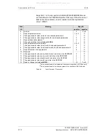
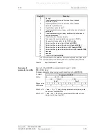
Page 21: ... RXnA Info flag 15 I15 RYnB Option flag 29 F29 RXnB Unused RYnC Monitor command RXnC Monitoring RYnD Frequency set command RAM RXnD Frequency setting complete RAM RYnE not used RXnE not used RYnF Command code execution request RXnF Command code execution complete RY n 1 0 RX n 1 0 RY n 1 1 RX n 1 1 RY n 1 2 RX n 1 2 RY n 1 3 Reserved RX n 1 3 Reserved RY n 1 4 RX n 1 4 RY n 1 5 RX n 1 5 RY n 1 6 R...

Page 22: ...dditional control bit refer to chapter 4 11 Optional flags in CBL profile RynC Monitor command When the monitor command is turned ON the monitor value is set in the remote register RWrm and the monitoring RXnC becomes ON The monitor value is constantly changed during ON Refer to chapter 4 5 Monitoring RynD Frequency set command RAM When the frequency set command is turned ON the frequency RWwm 1 i...

Page 23: ... Monitoring ON when the monitor value is set in RWrm while the monitor command RYnC is ON It turns OFF when the monitor command RYnC is turned OFF Refer to chapter 4 5 Monitoring RXnD Frequency setting complete RAM ON when frequency is written to the inverter while frequency set command RYnD is ON It turns OFF when the frequency set command RYnD is turned OFF Refer to chapter 4 4 Setpoint handling...

Page 24: ...ts the reference values setpoint and the actual values incl monitoring between CC Link interface and the dual port RAM interface of the MASTERDRIVES CBL translates between the different data formats by calculating with scaling factors The handling of parameters at CC Link by Command code execution is transformed to the PKW task handling with PKW request and reply of MASTERDRIVES remote IO bits rem...

Page 25: ...t is edge sensitive A 0 1 transition clears the error status If the fault in the converter is still active the error status can t be cleared Initial data setting is used by the PLC program to reset the CBL interface to CC Link Setpoints written to converter by frequency set command will be cleared also with this sequence RY n 1 9 RX n 1 9 RX n 1 B Initial data setting request Initial data setting ...

Page 26: ...fer of the converter They can parameterized from the panel of the converter PMU or from PLC via CC Link Working with variable setpoints They will be set with the frequency set command In the converter you can select softwiring one of the different sources by the parameter P443 Source main setpoint Refer to documentation of converter function diagram 316 At regulation of torque use P486 refer to do...

Page 27: ...setpoint 2 P402 xxxx speed RL xxxx fixed setpoint 3 P403 yyyy speed RM yyyy fixed setpoint 4 P404 zzzz speed RH zzzz After you have selected P443 0040 Source main setpoint fixed setpoint buffer you can control the speed by the control bits RL RM and RH If you activate more than one bit of them the lower speed has the higher priority The control bits JOG1 RYn5 and JOG2 Ryn7 have higher priority tha...

Page 28: ...you get actual values in register monitoring value RWrm You can change the monitor code during monitoring command is active But attention you don t know at which time you get actual values from the new selected process value Better you close the monitoring sequence change the monitor code and start a new sequence value a value a value b value b value b value b value a monitor code a monitor code b...

Page 29: ... format 8007h Optional actual value 7 MASTERDRIVES format 8008h Optional actual value 8 MASTERDRIVES format Table 4 3 Monitor code The monitoring values can be read in Mitsubishi inverter data format or MASTERDRIVES data format signed or unsigned refer to chapter 4 9 Data formats and data conversion You select your data format by the parameters P715 till P718 The monitor values with monitor code 0...

Page 30: ... of the parameter is written into written data RWwm 3 After that the sequence is activated with the control bit command code execution request After CBL has handled the command it acknowledges by writing a reply code RMrm 2 and read data RMrm 3 and then activating command code execution complete RYnF RWwm 2 RXnF RWrm 2 command code reply code Command code execution request Command code Command cod...

Page 31: ...rameter number The parameter ID PKE is always a 16 bit value Bits 0 to 10 PNU contain the number of the required parameter The meaning of the parameters can be found in the section Parameter list of the converter operating instructions Bit 11 SPM is the toggle bit for parameter change reports Parameter change reports are not supported by the CBL Bits 12 to 15 AK contain the task reply ID The meani...

Page 32: ...tive element not with CBL 3 6 Request parameter value array 1 4 or 5 7 Change parameter value array word for indexed parameters 2 4 8 Change parameter value array double word for indexed parameters 2 5 9 Request number of array elements 6 10 Reserved 11 Change parameter value array double word and store in the EEPROM2 5 12 Change parameter value array word and store in the EEPROM 2 4 13 Change par...

Page 33: ...word not with CBL 11 Parameter change report array word 2 not with CBL 12 Parameter change report array double word 2 not with CBL 13 Reserved 14 Reserved 15 Transfer text not with CBL 1 The required element of the parameter description is specified in IND 2nd word 2 The required element of the indexed parameter is specified in IND 2nd word Table 4 5 Reply ID converter master Source for the ON OFF...

Page 34: ...ng Converter parameter Access key and or Parameter special access not correctly set 15 No text array present 17 Task cannot be executed because of operating status Converter status does not permit the set task at the moment 101 Parameter number deactivated at present 102 Channel width too small 103 PKW number incorrect 104 Parameter value not admissible 105 The parameter is indexed In the case of ...

Page 35: ...the required element is transferred The meaning of the descriptive elements can be found in the PROFIBUS profile for variable speed drives VDI VDE 3689 Source for the ON OFF1 command control word 1 bit 0 P554 22A Hex Change parameter value of index 1 2nd word Parameter index IND Bit No 15 8 7 0 Byte 3 Byte 2 Binary value 0 0 0 0 0 0 0 0 0 0 0 0 0 0 0 1 HEX value 0 0 0 1 Bits 8 to 15 Bits 0 to 7 In...

Page 36: ...lue PWE 3rd word PWE1 Byte 5 Byte 4 Bit No 15 8 7 0 HEX value 3 1 0 0 4th word PWE2 Byte 7 Byte 6 Bit No 31 24 23 16 HEX value 0 0 0 0 Bits 8 to 15 Bits 16 to 31 Parameter value in the case of 16 bit parameter or low component in the case of 32 bit parameter Value 0 in the case of 16 bit parameter or high component in the case of 32 bit parameter Example Parameter value All manuals and user guides...

Page 37: ...the user sends a PKE Command PKE information and low word PWE1 is transported to CBL CBL merges the data PKE IND PWE1 and PWE2 and sends an PKW request to the converter Receiving the PKW reply from converter CBL acknowledges the PKE Command from user with a reply code and the verified PWE1 If the user has a 32 bit operand he can read the high word PWE2 by an READ Command PKW request PKE IND PWE1 P...

Page 38: ...mand have additional features Refer to the documents of the converter CBL transports all bits except bit 10 and 11 transparent to the converter Starting a PKE Command first write the PKE information in register command code RWwm 2 Bit 11 has to be 0 If you want to write a parameter put the data word bit 15 0 or lower word from 32 bit operand into register written data RWwm 3 Now you can activate c...

Page 39: ...it operand you don t need the READ Command Reply code Meaning 0000 Positive reply at INDEX Command and READ Command 0003 Positive reply at PKE Command PKW reply delivers 16 bit data in PWE1 0004 Positive reply at PKE Command PKW reply delivers 32 bit data low word in PWE1 high word in PWE2 8004 Negative reply at PKE Command no PKW reply from converter timeout 40 seconds 8006 Negative reply at PKE ...

Page 40: ...You want to read to an indexed array word 16 bit Task ID is 6 PKE bit 15 12 Parameter 443 decimal is 1BBh hexadecimal After you have activated the command code execution you get the acknowledge command complete from CBL You see Reply Code RWrm 2 0003h Read Data RWrm 3 3002h Reply code 0003 indicates there was no error and the answer is a 16 bit word reply code 0004 means 32 bit word P443 3002 show...

Page 41: ...the additional error code 0011h 17 decimal 17 Task cannot be executed because of operating status The error message occurs when you try to change the setpoint channel with the motor running 3 Write parameter P443 0040 converter not in RUN mode INDEX Command Command Code RWwm 2 0801h Written Data RWwm 3 irrelevant You get the reply Reply Code RWrm 2 0000h Read Data RWrm 3 irrelevant PKE Command Com...

Page 42: ...h C000h 4000 0000h 0000 0000h C000 0000h 100 0 100 Table 4 9 SIMOVERT MASTERDRIVES internal data format The display of SIMOVERT MASTERDRIVES shows the absolute value For this reason there are parameters with scaling factors e g P350 P353 Their contents are the absolute value at 100 CBL has to convert the data from Mitsubishi data format in MASTERDRIVES data format and vice versa The CBL uses param...

Page 43: ...ts STF RYn0 and STR RYn1 CBL doesn t convert the setpoints Actual values and monitoring values are converted to unsigned integer In this case you have to set the parameter P715 0 current P716 0 voltage P717 0 frequency P718 0 rotation per minute The CB parameters P715 P718 are pointers to scaling parameters If a CB parameter P715 P718 is 0 the corresponding type of process value isn t converted by...

Page 44: ... this case between 0 and 7FFFh 0 200 e g set frequency 1000h 25 Values greater than 7FFFh will be set to 7FFFh If P717 greater than 0 P717 is a pointer to scaling parameter the unsigned integer value corresponds to the frequency value e g set frequency 2000 20 00 Hz Torque control Set frequency RWwm 1 unsigned 16 bit integer fixed scaling parameter torque MASTERDRIVES format signed 16 bit 200 200 ...

Page 45: ...0 P717 0 P717 xxx Reverse operation RXn1 0 0 Forward operation RXn0 Actual value PZD2 signed 16 bit value MASTERDRIVES format 200 200 FFFFh Fig 4 10 Data conversion at actual value channel At torque control there is a fixed scaling parameter instead of P717 So torque actual values everytime converted from signed MASTERDRIVES value 200 200 into unsigned integer format of Mitsubishi inverter Monitor...

Page 46: ...erter The drive stops Remark Set P722 Telegram failure time to 0000 P712 bit 0 0 HOLD function When communication breaks down CBL detects the fault CBL don t react It gives no further information telegrams to the converter Actual control bits and setpoint are further valid Drive is still running Now you can handle the fault reaction by the fault mechanism of the converter With converter parameter ...

Page 47: ...e 16 bit word to your special function of your application Example If you want to use the function OFF3 quick stop from the PLC route e g P558 3411 Parameter P558 is one of three inputs and function of control word bit OFF3 B3411 is the binector PZD4 bit 11 of the first communication board refer to function diagrams 120 and 180 of converter documentation The infoflags give you additional informati...

Page 48: ...All manuals and user guides at all guides com ...

Page 49: ... the documentation and function diagrams of the converter and check the connector numbers 5 1 Basic parameterization of the units Optional boards CBL Yes P060 4 Function selection hardware configuration CB Parameter for CBL P711 0 4 P712 0 255 P715 typ 350 P716 typ 351 P717 typ 352 P718 typ 353 P918 1 64 Data transmission rate Option switch Scaling parameter A Scaling parameter V Scaling parameter...

Page 50: ...rs E g P053 1 Parameterizing enable only CBL 3 Parameterizing enable CBL PMU 7 Parameterizing enable CBL PMU SST1 OP If the parameter change parameterizing enable is enabled via the CBL P053 1 3 etc all further parameters can be set from the CC Link master via the bus P060 Function selection Hardware setting 4 P711 CB parameter 1 Communication speed CC Link With this parameter the data transmissio...

Page 51: ...iagnostic refer to chapter 6 3 Evaluation of the CBL diagnostic parameter Default value of P712 is 0 P712 Reserved Bit 2 Bit 1 Bit 0 Bit 0 0 hold function on communication breakdown 1 clr function on communication breakdown Bit 1 0 speed control of the motor 1 torque control Bit 2 0 diagnostic data r732 14 r732 25 CC Link data Master CBL CBL Master 1 diagnostic data r732 14 r732 25 parameter data ...

Page 52: ...l contents P715 Pointer to scaling parameter current P350 P716 Pointer to scaling parameter voltage P351 P717 Pointer to scaling parameter frequency P352 P718 Pointer to scaling parameter revolutions per minute P353 Example P715 0 and P717 352 The monitoring value output current has the original MASTERDRIVES internal data format not modified The process values set frequency and actual frequency in...

Page 53: ...the dual port RAM the following measures must be taken for safety reasons An OFF2 or OFF3 command see instruction manual of the converter section Control word must be additionally parameterized to the terminal strip PMU as otherwise the converter can no longer be turned off by means of a defined command if the communications system breaks down P781 i13 fault delay With this parameter P781 13 fault...

Page 54: ...ticular PZDi in the dual port RAM To do this the connector belonging to the desired PZDi is assigned to the selection switch Control words STW1 and STW2 are also available in bits on so called binectors within CUMC CUVC and Compact PLUS For an explanation of the BICO system see Section Function blocks and parameters For connecting the MASTERDRIVES converter to CC Link a defined set of softwiring h...

Page 55: ...ata transmission between PLC cpu and CBL the alarm message A035 will occur and will be displayed control bits 11 and 12 equals 0 The duration depends on the converter type and the configuration tech board plugged and takes some seconds After starting data transmission via CC Link to PLC cpu the alarm will be automatically cleared Parameter Contents Meaning Controlword 2 connecting CBL controlword ...

Page 56: ...datory if the converter is controlled by Frequency Set Command at the PLC Setpoint by RL RM RH connecting fixed setpoint buffer of converter to converter setpoint input P443 0040 Mandatory if the converter is controlled by control bits RL RM and RH in the PLC P417 P418 0 0 Mandatory Higher select bits of fixed setpoint buffer P401 0000 Setpoint 0 P402 xxxx Setpoint activated by RL P403 xxxx Setpoi...

Page 57: ...734 5 0021 0189 Mandatory actual value output voltage P734 6 0070 Mandatory setpoint frequency P734 7 0148 0151 Mandatory actual value rotation P734 8 0024 Mandatory actual value torque P734 9 xxxx Optional Optional monitoring value 1 P734 10 xxxx Optional Optional monitoring value 2 P734 11 xxxx Optional Optional monitoring value 3 P734 12 xxxx Optional Optional monitoring value 4 P734 13 xxxx Op...

Page 58: ...All manuals and user guides at all guides com ...

Page 59: ...ission errors CRC or hardware faults RUN Receive refresh and polling frames normally LED Status Diagnostic information CBL Red Flashing CBL in operation voltage supply on Yellow Flashing Fault free data exchange with the basic unit Green Flashing Fault free process data transfer via the CC Link Table 6 1 Status display of the CBL LED Status Diagnostic information CC Link RDLED Continuously lit Det...

Page 60: ...an unusual operating status parameterization phase or fault During normal operation the green CC Link LEDs are continuously lit The yellow one is off Diagnostic sequence LED off LED flashing LED continuous lit LED information irrelevant CBL status LEDs CC Link interface LEDs Refer to RED YELLOW GREEN RDLED SDLED RUNLED ERRLED Case 1 Case 2 Case 3 Case 4 Case 5 Case 6 Case 7 Case 8 Case 9 Case 10 o...

Page 61: ...e 6 5 Display during operation Communication error at DPRAM LED Status Diagnostic information CBL Red Flashing Yellow OFF Green Continuously lit CBL is waiting for start of parameterization initialization by the converter inverter This sequence is automatically started by CU after power up and re parameterizing CBL will stay in this status for some seconds till CU is initialized Table 6 6 Display ...

Page 62: ...ring operation CBL fetches scaling parameters LED Status Diagnostic information CBL Red Flashing Yellow Flashing Green OFF CBL now parameterized and has fetched the scaling parameters The CC Link interface is initialized Check CC Link interface LEDs Table 6 9 Display during operation CC Link initialized Now it is assumed that the CBL LEDs red and yellow are synchronous flashing LED Status Diagnost...

Page 63: ...ice station occupies 1 station with station number like P918 Table 6 12 Fault display during operation NO RUNLED at CBL LED Status Diagnostic information CC Link RDLED ON SDLED ON RUNLED ON ERRLED OFF CBL communicates correctly on CC Link O k Check CBL status LEDs Table 6 13 Display during operation CBL communicates on CC Link Now the three green CC Link status LEDs continuously lit Check the gree...

Page 64: ...D Flashing CBL detects data communication errors CRC error at data transmission Check Shield connection of the cable at housing of CU and at all CC Link stations EMC faults Check cable length of CC Link bus according to the data transmission rate Table 6 15 Fault display during operation CRC error at CC Link Case 10 All manuals and user guides at all guides com ...

Page 65: ...nd technology board not plugged Change parameter value A 085 Invalid P712 invalid switches bits are activated in P712 Check P712 and change parameter value A 086 CBL is waiting for scaling parameters CBL requests the scaling parameters and is waiting for reply Tech board or base board perhaps in initialization mode If CBL don t clear this warning after a time period Check converter status Check ba...

Page 66: ...Correct CB bus address CC Link P918 CBL defective Replace CBL F 081 DPR heartbeat The CBL is no longer processing the heartbeat counter CBL not correctly inserted into the electronics box Check CBL CBL defective Replace CBL F 082 DPR telegram failure The telegram failure time set by means of parameter P722 has expired PLC bus master failed green LED on the CBL is continuously off Check PLC cpu and...

Page 67: ...r for timeouts r732 7 Assigned internally r732 8 Reserved r732 9 Counter for detected Initial Data Setting Sequences r732 10 Counter for detected Frequency Set Commands r732 11 Counter for detected Command Requests r732 12 Counter for activated PKW requests r732 13 P712 Bit 2 0 P712 Bit 2 1 M R_Yn 00 0F PKW request PKE r732 14 M R_Yn 10 1F IND r732 15 M R_RWwm 0 monitor code PWE1 r732 16 M R_RWwm ...

Page 68: ...ACT VALUE channel double words routed 09 Incorrect configuration sequence 0A Reserved Table 6 19 CBL diagnostics buffer configuration error r732 02 Counter received telegrams without fault ONLINE Counter for telegrams received error free with data transfer between PLC and CBL r732 03 Counter received telegrams without fault OFFLINE Counter for telegrams received error free with no data transfer be...

Page 69: ...7 r732 18 r732 19 Data from PLC CC Link M RYn 00 0F M RYn 10 1F M R_RWwm 0 monitor code M R_RWwm 1 frequency set command M R_RWwm 2 command code M R_RWwm 3 written data r732 20 r732 21 r732 22 r732 23 r732 24 r732 25 Data to PLC CC Link R MXn 00 0F R MXn 10 1F R M_RWrm 0 monitor value R M_RWrm 1 actual frequency R M_RWrm 2 command reply R M_RWrm 3 read data P712 Bit 2 1 Diagnostic page selection P...

Page 70: ...All manuals and user guides at all guides com ...

Page 71: ...ange 10 Hz to 58 Hz 19 6 m s2 in the frequency range 58 Hz to 500 Hz 3 5 mm in the frequency range 5 Hz to 9 Hz 9 8 m s2 in the frequency range 9 Hz to 500 Hz Climatic class Class 3K3 to DIN IEC 721 3 3 during operation Type of cooling Natural air cooling Permissible ambient or cooling medium temperature during operation during storage during transport 0 C to 70 C 32 F to 158 F 25 C to 70 C 13 F t...

Page 72: ...All manuals and user guides at all guides com ...

Page 73: ... actual value RXn1 Polarity of actual value RXn2 Statusword bit 2 RXn3 Statusword bit 8 RXn4 Statusword bit 22 RXn5 Statusword bit 11 RXn6 Statusword bit 10 RXn7 Statusword bit 3 RXn8 Statusword bit 0 RXn9 Statusword bit 7 RXnA Statusword bit 15 RXn 1A Statusword bit Bit 3 CBL bit conversion from converter to CC Link interface All manuals and user guides at all guides com ...

Page 74: ...OG1 9 JOG2 10 1 11 STF STR 12 See below 13 0 14 0 15 0 16 RT 0 00 17 RT 1 01 18 0 19 0 20 RH 11 RM 10 21 RL 01 22 0 23 1 24 1 25 1 26 0 27 F27 28 F28 29 F29 30 0 31 0 Remote IO Bits Controlword STF STR Forward enable Bit 11 Reverse Enable Bit 12 0 0 1 1 1 0 1 0 0 1 0 1 1 1 1 1 CBL bit conversion from CC Link interface to converter All manuals and user guides at all guides com ...

Page 75: ...477 761 4070 76 J AA 76 A5E00387649 Version AA consists of the following chapters Chapter Changes Pages Version date 1 Definitions and Warnings first edition 3 03 99 2 Description first edition 5 03 99 3 Connecting up first edition 6 03 99 4 Communication via CC Link first edition 27 03 99 5 Start up of the CBL first edition 9 03 99 6 Diagnosis and troubleshooting first edition 11 03 99 7 Technica...

Reviews: