background image

Faults 


SIMOTICS S-1FG1 servo geared motor 

136


Operating Instructions, 07/2019, A5E47360747B AA 

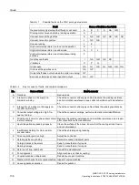
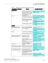
Table 8- 1 

Possible faults on the 1FG1 servo geared motor 

Fault 

Cause of fault (see key table) 

Geared motor only starts with difficulty or not at all 

 F 

GA  GR 


Droning motor noise on startup / during operation 

 F 


Unusual noise at the gearbox 

GA 

GB  GC  GD  GE  GH 

Unusual noise at converter. 

GC  GE 


Uneven running 


High motor temperature rise in no-load operation 

I  


High motor temperature rise under load 

J     


High motor temperature rise of individual winding 

sections 


Gearbox overheats. 

GA  GR  GS  GC   


Vibrations 

P  


Oil escapes. 

GA 

GI 

GK  GL  GM  GN  GO 

Oil leak at the gearbox vent. 

GA 

GP   


Output shaft does not turn when the motor is running.  GT   


Excessive clearance at drive input and output. 

GU 

GV   


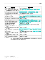
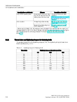
Table 8- 2 

Key to causes of faults, and remedial measures 

No. 

Cause of fault 

How to remedy 

A  Overload 

Reduce load 

B  Interrupted phase in the supply ca-

ble/motor winding 

Check the converter and supply cables/measure the winding resistanc-

es and insulation resistances, repair after consultation with manufactur-

er 

C  Interruption of a phase in the supply ca-

ble after switching on 

Check the converter and supply cables/check the winding resistances 

D  Converter output voltage too high, fre-

quency too low 

Check the converter settings, perform automatic motor identification. 

F  Winding short circuit or phase short circuit 

in stator winding 

Measure the winding resistances and insulation resistances, and repair 

after consultation with manufacturer 

Heat dissipation impeded by deposits 

Clean the surface of the drives. Ensure that the cooling air can flow in 

and out unimpeded. 

Insufficient shielding for motor and/or 

encoder cable 

Check the shielding and grounding 

K  Drive controller gain too high 

Adjust the controller. 

Rotating parts are grinding 

Determine cause and adjust parts 

Foreign bodies in the motor 

Send to manufacturer for repair 

Bearing damage 

Send to manufacturer for repair 

N  Rotor out of true, shaft bent 

Consult the manufacturer 

O  Poor alignment 

Align machine set, check coupling. 

P  Coupled machine not balanced 

Rebalance coupled machine. 

Q  Mechanical shocks from coupled machine  Inspect coupled machine. 
R  Uneven gearbox operation 

Repair the gearbox. 

Summary of Contents for SIMOTICS S-1FG1

Page 1: ...SIMOTICS S 1FG1 servo geared motor ...

Page 2: ......

Page 3: ...tructions 07 2019 A5E47360747B AA Introduction Fundamental safety instructions for the SIMOTICS documentation 1 Description 2 Preparing for use 3 Mounting 4 Connecting 5 Commissioning 6 Operation 7 Faults 8 Service and maintenance 9 Decommissioning and disposal 10 Appendix A ...

Page 4: ... by personnel qualified for the specific task in accordance with the relevant documentation in particular its warning notices and safety instructions Qualified personnel are those who based on their training and experience are capable of identifying risks and avoiding potential hazards when working with these products systems Proper use of Siemens products Note the following WARNING Siemens produc...

Page 5: ...ctly and safely The operating instructions inform you about how to handle the SIMOTICS S 1FG1 servo geared motor from delivery to final disposal Before you start using the 1FG1 servo geared motor you must read these Operating Instructions to ensure safe problem free operation and to maximize the service life Siemens strives continually to improve the quality of information provided in these Operat...

Page 6: ...ng instructions Enumerations Enumerations are identified by a bullet point without any additional symbols Enumerations at the second level are hyphenated Notes Notes are shown as follows Note A Note is an important item of information about the product handling of the product or the relevant section of the document Notes provide you with help or further suggestions ideas More information Informati...

Page 7: ...ww siemens com motioncontrol Websites of third parties This publication contains hyperlinks to websites of third parties Siemens does not take any responsibility for the contents of these websites or adopt any of these websites or their contents as their own because Siemens does not control the information on these websites and is also not responsible for the contents and information provided ther...

Page 8: ...Introduction SIMOTICS S 1FG1 servo geared motor 6 Operating Instructions 07 2019 A5E47360747B AA ...

Page 9: ...ating factors 24 2 4 Structure of the article number 25 2 5 Rating plate specifications of the servo geared motor 28 2 6 Type designation of the gearbox 29 2 7 Mounting and options 30 2 7 1 Warning labels on the servo geared motor 30 2 7 2 Cooling of the servo geared motor 31 2 7 3 Holding brake 31 2 7 3 1 Properties 31 2 7 3 2 Motor side connection of the holding brake 32 2 7 3 3 Protective circu...

Page 10: ... Torque arms with shaft mounted gearboxes 100 4 10 Mount the oil expansion unit 103 4 11 Vibration response 106 5 Connecting 107 5 1 Safety instructions 107 5 2 Permissible line system types 108 5 3 Circuit diagram 108 5 4 System integration 109 5 4 1 Connection notes 109 5 4 1 1 Motor connection 109 5 4 1 2 Rotating the connector at the motor 111 5 4 2 Power connection 113 5 4 3 Signal connection...

Page 11: ...evel using the oil sight glass optional 147 9 2 4 3 Checking the oil quality 147 9 2 4 4 Changing the oil 148 9 2 4 5 Recommended oil types 152 9 2 4 6 Change the roller bearing grease 152 9 2 4 7 Service life of the lubricants 153 9 2 4 8 Recommended lubricants 154 9 2 4 9 Oil quantities 156 9 2 5 Checking the gearbox for leaks 156 9 2 6 Cleaning the gearbox 157 9 2 7 Checking tightness of fasten...

Page 12: ...Table of contents SIMOTICS S 1FG1 servo geared motor 10 Operating Instructions 07 2019 A5E47360747B AA ...

Page 13: ...bels has elapsed 4 Check that there is no voltage between any of the power connections and between any of the power connections and the protective conductor connection 5 Check whether the existing auxiliary supply circuits are de energized 6 Ensure that the motors cannot move 7 Identify all other dangerous energy sources e g compressed air hydraulic systems or water Switch the energy sources to a ...

Page 14: ...ed housing potential WARNING Electric shock if there is no ground connection For missing or incorrectly implemented protective conductor connection for devices with protection class I high voltages can be present at open exposed parts which when touched can result in death or severe injury Ground the device in compliance with the applicable regulations WARNING Arcing when a plug connection is open...

Page 15: ... accidents resulting in serious injury or death Check that the warning labels are complete based on the documentation Attach any missing warning labels to the components where necessary in the national language Replace illegible warning labels WARNING Unexpected movement of machines caused by inactive safety functions Inactive or non adapted safety functions can trigger unexpected machine movement...

Page 16: ...If you have a heart pacemaker or implant maintain the minimum distance specified in chapter Correct usage When transporting or storing permanent magnet motors always use the original packing materials with the warning labels attached Clearly mark the storage locations with the appropriate warning labels IATA regulations must be observed when transported by air WARNING Injury caused by moving or ej...

Page 17: ...tenance is required Allow the motor to cool down before starting any work Use the appropriate personnel protection equipment e g gloves 1 1 2 Equipment damage due to electric fields or electrostatic discharge Electrostatic sensitive devices ESD are individual components integrated circuits modules or devices that may be damaged by either electric fields or electrostatic discharge NOTICE Equipment ...

Page 18: ... development to make them more secure Siemens strongly recommends that product updates are applied as soon as they become available and that only the latest product versions are used Use of product versions that are no longer supported and failure to apply the latest updates may increase customer s exposure to cyber threats To stay informed about product updates subscribe to the Siemens Industrial...

Page 19: ...al influences damage X ray ionizing radiation and cosmic radiation 2 Unusually high temperatures including open flames as well as emissions of light noise particles gases etc can occur inside and outside the components under fault conditions caused by for example Component failure Software errors Operation and or environmental conditions outside the specification External influences damage 3 Hazar...

Page 20: ...Fundamental safety instructions for the SIMOTICS documentation 1 1 Fundamental safety instructions SIMOTICS S 1FG1 servo geared motor 18 Operating Instructions 07 2019 A5E47360747B AA ...

Page 21: ...r operation without external cooling and the heat is dissipated through the motor surface The 1FG1 servo geared motors have a high overload capability 2 1 Use for intended purpose WARNING Motors not used for the intended purpose If you do not use the motors correctly there is a risk of death severe injury and or material damage Only use the motors for their intended purpose Make sure that the cond...

Page 22: ...ructions is part of correct usage Observe the details on the rating plate 2 2 Technical features and ambient conditions 2 2 1 Directives and standards Standards that are complied with The motors of the type series SIMOTICS S SIMOTICS M SIMOTICS L SIMOTICS T SIMOTICS A called SIMOTICS motor series below fulfill the requirements of the following directives and standards EN 60034 1 IEC 60034 1 Rotati...

Page 23: ...IMOTICS motor series complies with the 2012 19 EU directive on taking back and recycling waste electrical and electronic equipment Eurasian conformity SIMOTICS motors comply with the requirements of the Russia Belarus Kazakhstan EAC customs union China Compulsory Certification SIMOTICS motors do not fall within the scope covered by the China Compulsory Certification CCC CCC negative certification ...

Page 24: ...water alone is not adequate for liquids that contain oil can creep and or are aggressive In such cases protect the servo geared motor with a suitable cover Temperature monitoring Temperature sensor in the stator winding Paint finish Anthracite similar to RAL 7016 Sound pressure level LpA 1 m according to DIN EN ISO 1680 max tolerance 3 dB A 1FG1 C SH 36 1FG1 D SH 48 1FG1 E SH 63 1FG1 F SH 80 1FG1 ...

Page 25: ...ve humidity 5 d High relative humidity 95 e Low absolute humidity g m3 1 f High absolute humidity g m3 29 g Rate of temperature change1 C min 0 5 h Low air pressure4 kPa 70 i High air pressure2 kPa 106 j Solar radiation insolation W m2 700 k Thermal radiation l Air movement3 m s 1 0 m Condensation Not permissible n Wind driven precipitation rain snow hail etc o Water other than rain See degree of ...

Page 26: ...de 1000 m above sea level the permissible torques powers are shown in the following table Ambient temperatures and installation altitudes are rounded off to 5 C or 500 m respectively Table 2 2 Power derating depending on the installation altitude and the ambient temperature Installation altitude above sea level in m Ambient temperature in C 30 35 40 45 50 55 1000 1 05 1 02 1 00 0 97 0 95 0 92 1500...

Page 27: ...775 5000 0 656 6000 0 588 7000 0 513 8000 0 444 As the DC link voltage is reduced the converter output voltage also decreases Operation in a vacuum is not permissible because of the low dielectric strength and poor heat dissipation 2 4 Structure of the article number The following overview describes the structure of the article number The article number comprises a combination of digits and letter...

Page 28: ...worm geared motors 2 stage gearbox type C 1 F G 1 6 Gearbox size Output shaft variants Solid shaft standard type 1 1 Solid shaft standard type 2 2 Solid shaft standard type 3 3 Hollow shaft standard type 1 5 Hollow shaft standard type 2 6 Hollow shaft standard type 3 7 Hollow shaft special shaft design for more infor mation see Chapter Options 9 Encoder AS20DQI Q Encoder AM20DQI R Encoder AM20DQI ...

Page 29: ...r version CT Com pact 2 Line voltage 200 240 V 1 AC DC link voltage 270 330 V DC in motor version HD High Dynamic 3 Line voltage 380 480 V 3 AC DC link voltage 510 720 V DC in motor version HD High Dynamic 4 Foot mounted design A Foot flange mounted design for flange mounted design see Chapter Options in Catalog D41 B Shaft mounted design torque arm Only for servo bevel geared motors 3 stage For t...

Page 30: ...s for Y84 17 Maximum output torque during short time duty M2dyn Nm 5 Gearbox type 18 Max permissible speed input side during short time duty n1max rpm 6 Gearbox oil gearbox oil quantity M0bilgear l 19 Max permissible speed output side during short time duty n2max rpm 7 Permanent static torque Mo Nm 20 Stall current I0 A 8 Induced voltage UiN V 21 Maximum current Imax A 9 Encoder type 22 Degree of ...

Page 31: ...arbox three stage F Parallel shaft gearbox C Helical worm gearbox Stage Z Two stage D Three stage Type Shaft Solid shaft A Hollow shaft Fixing Foot mounted design B Foot flange mounted design F Flange mounted design A type Z Housing flange C type D Torque arm Connection Feather key S Shrink disk T Hollow shaft with splines R SIMOLOC Table 2 5 Example of the type designation structure Example F D A...

Page 32: ...umber Helical gearbox Two stage Z 1 Helical gearboxes Three stage D 2 Parallel shaft gearbox F Two stage Z 3 Parallel shaft gearbox F Three stage D 4 Bevel gearbox B K Two stage three stage 5 Helical worm gearbox C Two stage 6 2 7 Mounting and options 2 7 1 Warning labels on the servo geared motor The following warning labels are attached to the 1FG1 servo geared motor Warning symbol Warning again...

Page 33: ...aces If the gearbox housing temperature exceeds a value of 80 C please contact Technical Support 2 7 3 Holding brake 2 7 3 1 Properties The holding brake is used to clamp the motor shaft when the motor is at a standstill The holding brake is not a working brake for braking the rotating motor The holding brake can be implemented as a permanent magnet brake or a spring loaded brake WARNING Danger to...

Page 34: ...application of the holding brake The holding brake must not be used in hazardous areas or in areas subject to firedamp Note Subsequent conversion of motors with or without a holding brake is not possible Motors with a holding brake are longer by the installation space required for the holding brake Setting up the brake The rated voltage of the holding brake is 24 V DC 10 Voltages outside this tole...

Page 35: ...ltage peaks with a protective circuit See the figure Suggested circuit for the external power supply The protective circuit also ensures the specified switching times See the table Technical data of the holding brakes used To ensure fault free release of the brake a minimum voltage of 24 V DC 10 must be applied to the connector on the motor side If the maximum voltage of 24 V DC 10 is exceeded the...

Page 36: ...ke The magnetic field of the permanent magnets exerts a pulling force on the armature disk of the holding brake This means that in the no current condition the brake is closed and the motor shaft is held closed circuit principle When 24 V DC rated voltage is applied to the brake the current carrying coil produces an opposing field This neutralizes the force of the permanent magnets and the brake o...

Page 37: ...f the machine or installation You can release the braking effect of the spring loaded brake with the mechanical manual brake release Unintended movements of the machine or installation can result in death or serious injury Mount the braking resistors so that unintended actuation of the manual release handle is not possible Place the manual release handle in the vertical position to ensure the full...

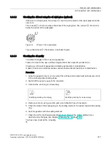
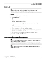
Page 38: ...uring the manual brake release In the unactuated state the manual release handle must be in the vertical position see figure Only in this position is the brake fully closed and the full braking effect ensured The manual release handle can only be removed in the vertical position Procedure Figure 2 3 Removing the manual release handle of the spring loaded brake 1 Place the manual release handle in ...

Page 39: ...les When opening the cover of the air gap check loose particles can be ejected and cause injury Switch the motor off before opening the cover Open the cover only when the motor is at a standstill Before switching the motor on again close the cover of the air gap check With the mechanical air gap check you can check the width of the air gap s of the spring loaded brake The width of the air gap indi...

Page 40: ...3 Calculate the distance s between the brake housing and the armature disk using a thickness gauge 4 Compare the calculated width of the air gap with the table below 1FG1 F 1FG1 G Air gap s mm in new state 0 20 0 03 0 20 0 03 Maximum permissible air gap smax mm at 70 of the rated current 0 44 0 70 You have checked the wear state of the armature disk When the air gap reaches the value smax the wear...

Page 41: ...ce test The relevant certificate can be found on the Internet at Certificate https support industry siemens com cs ww en view 58657336 For more information about the certificate see Chapter Certificate for the PS Premium painting system from ECOLAB Page 163 The resistance only applies to the painted parts You must take suitable protective measures for non painted parts below Shafts in hollow shaft...

Page 42: ...Description 2 7 Mounting and options SIMOTICS S 1FG1 servo geared motor 40 Operating Instructions 07 2019 A5E47360747B AA ...

Page 43: ... stack ISO 7000 No 2403 Scope of delivery of a servo geared motor Upon receipt of the delivery check immediately whether the items delivered are in accordance with the accompanying documents Note Siemens will not accept any claims relating to items missing from the delivery and which are submitted at a later date Register a complaint about any apparent transport damage with the transport company i...

Page 44: ... the servo geared motor Never commission faulty or defective servo geared motors Check the servo geared motor for completeness and for damage Report any missing parts or damage immediately Remove and dispose of the packaging material and transport fixtures in accordance with local national regulations 3 2 Transportation and storage 3 2 1 Transporting the servo geared motor Note Comply with the loc...

Page 45: ...the servo geared motor by the lifting eyes or eyebolts in the gearbox housing Because they are designed only for the weight of the geared motor it is not permissible to add additional loads to the lifting eyes and eyebolts Use a crossbar for lifting and transporting the servo geared motor Procedure 1 Screw the lifting eyes eyebolts in at appropriate locations for the orientation of the servo geare...

Page 46: ...lative humidity 75 Long term storage Note In the case of storage in transit over 6 months special arrangements must be made for preservation Contact Technical Support If you store the servo geared motor for longer than six months the storage facility must satisfy the following conditions The 1FG1 servo geared motor is protected against extreme weather conditions The facility air must be free from ...

Page 47: ...iron Bevel gearbox B Aluminum Aluminum Aluminum Cast iron Bevel gearbox K Aluminum Cast iron Cast iron Cast iron Helical worm gearbox C Aluminum Cast iron Cast iron Cast iron Geared components The geared components are hardened and ground For the helical worm gearbox the worm is hardened and ground The gear is manufactured from high quality bronze The bevel gear stage of the bevel gearbox is lappe...

Page 48: ...nmental stress optional The sealing ring is equipped with an additional fiber disk In addition to the longer service life the disk also provides increased protection against higher environmental stress as a result of moisture and dust Noise The geared motors are certified for a wide range of installation and operating conditions Conditions such as rigid or vibration isolated foundation design infl...

Page 49: ... 29 are lubricated for life These gearboxes have no openings for checking the oil level Mounting positions M2 and M4 are equipped with a vent valve C29 has a vent valve in all mounting positions Table 3 4 Symbols Oil valves Symbol Meaning Identifying marking of vent plug Identifying marking for ventilation opposite side Identifying marking for oil level plug Identifying marking for oil level oppos...

Page 50: ...s SIMOTICS S 1FG1 servo geared motor 48 Operating Instructions 07 2019 A5E47360747B AA 3 4 1 Two and three stage helical gearbox Figure 3 1 Mounting positions for helical gearboxes Z and D foot mounted design sizes 19 29 2 stage and 3 stage ...

Page 51: ...3 4 Mounting positions SIMOTICS S 1FG1 servo geared motor Operating Instructions 07 2019 A5E47360747B AA 49 Figure 3 2 Mounting positions for helical gearboxes Z and D foot mounted design sizes 39 129 2 stage and 3 stage ...

Page 52: ...Mounting positions SIMOTICS S 1FG1 servo geared motor 50 Operating Instructions 07 2019 A5E47360747B AA Figure 3 3 Mounting positions for helical gearboxes ZB and DB foot flange mounted design sizes 19 29 2 stage and 3 stage ...

Page 53: ...Mounting positions SIMOTICS S 1FG1 servo geared motor Operating Instructions 07 2019 A5E47360747B AA 51 Figure 3 4 Mounting positions for helical gearboxes ZB and DB foot flange mounted design sizes 39 89 2 stage and 3 stage ...

Page 54: ...itions SIMOTICS S 1FG1 servo geared motor 52 Operating Instructions 07 2019 A5E47360747B AA Figure 3 5 Mounting positions for helical gearboxes DF and ZF flange design and DZ and ZZ housing flange design sizes 19 29 2 stage and 3 stage ...

Page 55: ...ositions SIMOTICS S 1FG1 servo geared motor Operating Instructions 07 2019 A5E47360747B AA 53 Figure 3 6 Mounting positions for helical gearboxes DF and ZF flange design and DZ and ZZ housing flange design size 39 2 stage and 3 stage ...

Page 56: ...itions SIMOTICS S 1FG1 servo geared motor 54 Operating Instructions 07 2019 A5E47360747B AA Figure 3 7 Mounting positions for helical gearboxes DF and ZF flange design and DZ and ZZ housing flange design sizes 49 129 2 stage and 3 stage ...

Page 57: ...ons SIMOTICS S 1FG1 servo geared motor Operating Instructions 07 2019 A5E47360747B AA 55 3 4 2 Parallel shaft gearbox Figure 3 8 Mounting positions for parallel shaft gearboxes FZ and FD foot mounted design sizes 19 29 2 stage and 3 stage ...

Page 58: ...ounting positions SIMOTICS S 1FG1 servo geared motor 56 Operating Instructions 07 2019 A5E47360747B AA Figure 3 9 Mounting positions for parallel shaft gearboxes FZ and FD foot mounted design sizes 39 129 2 stage and 3 stage ...

Page 59: ...IMOTICS S 1FG1 servo geared motor Operating Instructions 07 2019 A5E47360747B AA 57 Figure 3 10 Mounting positions for parallel shaft gearboxes FZ F and FD F flange design and FZ Z and FD Z housing flange design sizes 19 29 2 stage and 3 stage ...

Page 60: ...IMOTICS S 1FG1 servo geared motor 58 Operating Instructions 07 2019 A5E47360747B AA Figure 3 11 Mounting positions for parallel shaft gearboxes FZ F and FD F flange design and FZ Z and FD Z housing flange design sizes 39 129 2 stage and 3 stage ...

Page 61: ...nting positions SIMOTICS S 1FG1 servo geared motor Operating Instructions 07 2019 A5E47360747B AA 59 Figure 3 12 Mounting positions for parallel shaft gearboxes FZAD and FDAD shaft mounted design sizes 19 29 2 stage and 3 stage ...

Page 62: ...ting positions SIMOTICS S 1FG1 servo geared motor 60 Operating Instructions 07 2019 A5E47360747B AA Figure 3 13 Mounting positions for parallel shaft gearboxes FZAD and FDAD shaft mounted design sizes 39 129 2 stage and 3 stage ...

Page 63: ... 3 4 Mounting positions SIMOTICS S 1FG1 servo geared motor Operating Instructions 07 2019 A5E47360747B AA 61 3 4 3 Bevel gearbox Figure 3 14 Mounting positions for bevel gearbox B foot mounted design sizes 19 29 2 stage ...

Page 64: ...ng for use 3 4 Mounting positions SIMOTICS S 1FG1 servo geared motor 62 Operating Instructions 07 2019 A5E47360747B AA Figure 3 15 Mounting positions for bevel gearbox B foot mounted design sizes 39 49 2 stage ...

Page 65: ...4 Mounting positions SIMOTICS S 1FG1 servo geared motor Operating Instructions 07 2019 A5E47360747B AA 63 Figure 3 16 Mounting positions for bevel gearbox B Z flange design or B Z housing flange design sizes 19 29 2 stage ...

Page 66: ...4 Mounting positions SIMOTICS S 1FG1 servo geared motor 64 Operating Instructions 07 2019 A5E47360747B AA Figure 3 17 Mounting positions for bevel gearbox B Z flange design or B Z housing flange design sizes 39 49 2 stage ...

Page 67: ... for use 3 4 Mounting positions SIMOTICS S 1FG1 servo geared motor Operating Instructions 07 2019 A5E47360747B AA 65 Figure 3 18 Mounting positions for bevel gearbox BAD shaft mounted design sizes 19 29 2 stage ...

Page 68: ... for use 3 4 Mounting positions SIMOTICS S 1FG1 servo geared motor 66 Operating Instructions 07 2019 A5E47360747B AA Figure 3 19 Mounting positions for bevel gearbox BAD shaft mounted design sizes 39 49 2 stage ...

Page 69: ...g for use 3 4 Mounting positions SIMOTICS S 1FG1 servo geared motor Operating Instructions 07 2019 A5E47360747B AA 67 Figure 3 20 Mounting positions for bevel gearbox K foot mounted design sizes 39 149 3 stage ...

Page 70: ... Mounting positions SIMOTICS S 1FG1 servo geared motor 68 Operating Instructions 07 2019 A5E47360747B AA Figure 3 21 Mounting positions for bevel gearbox K F flange design and KAZ housing flange design sizes 39 149 3 stage ...

Page 71: ... for use 3 4 Mounting positions SIMOTICS S 1FG1 servo geared motor Operating Instructions 07 2019 A5E47360747B AA 69 Figure 3 22 Mounting positions for bevel gearbox KAD shaft mounted design sizes 39 149 3 stage ...

Page 72: ...unting positions SIMOTICS S 1FG1 servo geared motor 70 Operating Instructions 07 2019 A5E47360747B AA 3 4 4 Helical worm gearbox Figure 3 23 Mounting positions for helical worm gearbox C foot mounted design sizes 19 29 2 stage ...

Page 73: ...or use 3 4 Mounting positions SIMOTICS S 1FG1 servo geared motor Operating Instructions 07 2019 A5E47360747B AA 71 Figure 3 24 Mounting positions for helical worm gearbox C foot mounted design sizes 39 89 2 stage ...

Page 74: ...ounting positions SIMOTICS S 1FG1 servo geared motor 72 Operating Instructions 07 2019 A5E47360747B AA Figure 3 25 Mounting positions for helical worm gearbox CF flange design and CAZ housing flange design sizes 19 29 2 stage ...

Page 75: ...ounting positions SIMOTICS S 1FG1 servo geared motor Operating Instructions 07 2019 A5E47360747B AA 73 Figure 3 26 Mounting positions for helical worm gearbox CF flange design and CAZ housing flange design sizes 39 89 2 stage ...

Page 76: ...r use 3 4 Mounting positions SIMOTICS S 1FG1 servo geared motor 74 Operating Instructions 07 2019 A5E47360747B AA Figure 3 27 Mounting positions for helical worm gearbox CAD shaft mounted design sizes 19 29 2 stage ...

Page 77: ...r use 3 4 Mounting positions SIMOTICS S 1FG1 servo geared motor Operating Instructions 07 2019 A5E47360747B AA 75 Figure 3 28 Mounting positions for helical worm gearbox CAD shaft mounted design sizes 39 89 2 stage ...

Page 78: ...Preparing for use 3 4 Mounting positions SIMOTICS S 1FG1 servo geared motor 76 Operating Instructions 07 2019 A5E47360747B AA ...

Page 79: ...To hoist the motor use suitable cable guidance or spreading equipment particularly if the motor is equipped with built on assemblies The motor must not be lifted or transported by means of the power connector or signal connector Do not stand in the slewing range of hoisting gear or under suspended loads WARNING Danger to life from permanent magnet fields Even when switched off electric motors with...

Page 80: ...mage to gearbox components and bearings due to welding During welding work on the gearbox components in the gearbox can become unintentionally welded together due to the temperatures generated Do not carry out any welding work on the gearbox Do not use the gearbox as a grounding point for welding operations NOTICE Overheating caused by solar radiation Overheating of the gearbox due to exposure to ...

Page 81: ...sensitive parts for instance electric cables or electronic components come into contact with hot surfaces then these parts can be damaged Ensure that no temperature sensitive parts come into contact with hot surfaces 4 2 Checklists for mounting Note Required checks The checklists below do not purport to be complete It may be necessary to perform additional checks and tests in accordance with the s...

Page 82: ...with shrink disks or SIMOLOC connection See chapter Mounting or re moving the hollow shaft with shrink disk Page 91 or Installing or removing the SIMOLOC connection Page 95 4 3 Mounting instructions Note Technical data on the housing of the servo geared motor Comply with the technical data on the rating plates on the housing of the servo geared motor Comply with the data on the rating plate as wel...

Page 83: ...30 1 500 2 000 2 400 Tightening torques for screw plugs and valves The mounting tools to be used are a torque wrench or pneumatic or impact power screwdriver with automatic switch off Table 4 4 Tightening torque for screw plugs and valves Pipe thread according to DIN ISO 228 Part1 Tightening torque for brass screws Tightening torque for ferrous metal screws Tolerance 10 in Nm Tolerance 12 5 in Nm ...

Page 84: ...ation for the servo geared motor is free of distortion Build the foundation in such a way that no resonance vibrations are created and no vibrations are transmitted from adjacent foundations If the servo geared motor is fastened to a concrete foundation use foundation blocks for the appropriate recesses Align and grout the slide rails into the foundation Align the servo geared motor carefully and ...

Page 85: ... Use screws nuts of strength class 8 8 for gearboxes with a flange mounted design Note the following exceptions Table 4 7 Strength class of the fastening bolt for FF FAF and KF KAF Parallel shaft gearbox Bevel gearbox Flange Motor shaft heights 36 48 63 80 100 In flange mounted design Strength class of bolt nut F F F AF39 K F KAF39 A160 8 8 8 8 10 9 10 9 F F F AF49 K F KAF49 A200 8 8 8 8 8 8 8 8 1...

Page 86: ...ing option foot or flange is intended for add on elements that do not transmit any force e g protection covers with an intrinsic weight of up to max 30 of the weight of the gearbox 4 7 Mounting an input or output element on the gearbox shaft NOTICE Damage to shaft sealing rings caused by heating When mounting input and output elements with the heat treatment shaft sealing rings can be damaged by o...

Page 87: ...le 4 9 Stress on shafts and bearings Optimum Unfavorable low stress on shafts and bearings high stress on shafts and bearings Procedure 1 Use either petrol ether or solvent to remove the anti corrosion protection from the shaft ends and flanges or remove the applied protective skin 2 Heat the input or output elements if provided 3 Fit the drive input and output elements to the shafts 4 Secure the ...

Page 88: ...x housing Figure 4 2 Mounted protection cover for hollow shaft Procedure 1 Fit the output shaft 2 Use a suitable cleaning agent to clean the contact surface of the protection cover on the gearbox 3 Place the flat seal 4 Wet the screws with medium strength adhesive e g Loctite 243 5 Place the washers on the screws 6 Screw on the protection cover 7 Protect all remaining bare areas with a suitable pe...

Page 89: ...g on the contact surfaces by applying the enclosed mounting paste or a suitable greasing agent Note Observe the permissible concentricity tolerance of the cylindrical shaft end of the machine shaft to the housing axle according to DIN 42955 4 9 1 Mounting or removing the hollow shaft with feather key Mounting the hollow shaft with feather key Not included in scope of supply Machine shaft Circlip H...

Page 90: ...er key Table 4 10 Tightening torque for setscrews Thread size M5 M6 M8 M10 M12 M16 M20 M24 M30 Tightening torque in Nm 5 8 8 14 24 60 120 200 400 Removing the hollow shaft with feather key WARNING Danger to life due to falling gearboxes or geared motors Falling gearboxes or geared motors during removal can result in death or serious injury Before removing use adequately dimensioned load suspension...

Page 91: ...uded in the scope of supply Disk Threaded block Feather key Hexagon nut Threaded spindle Figure 4 4 Removing the hollow shaft with feather key Procedure 1 Remove the axial locking element from the hollow shaft 2 Drive out the machine shaft using the disk threaded block feather key threaded spindle and hexagon nuts You have now removed the hollow shaft with feather key ...

Page 92: ...15 10 19 9 10 M6 22 5 6 B F 29 25 3 15 10 24 9 16 M10 28 8 C 39 25 3 15 10 24 9 16 M10 28 8 B K F C 30 6 15 10 29 9 18 M10 33 8 B 35 6 15 10 34 9 24 M12 38 10 B 40 6 15 10 39 9 28 M16 43 12 C 49 30 6 15 10 29 9 18 M10 33 8 K F C 35 6 15 10 34 9 24 M12 38 10 B 40 6 15 10 39 9 28 M16 43 12 K F C 69 40 6 20 9 39 9 28 M16 43 12 C 45 6 20 9 44 9 36 M16 48 14 K F 79 40 6 20 9 39 9 28 M16 43 12 K F C 89 ...

Page 93: ...rom the shaft ends and flanges 2 Check the seats or edges of the hollow and machine shafts for damage Contact Technical Support if you notice any damage 3 Fit the gearbox with the shrink disk shaft onto the machine shaft Carefully ensure the correct position and that the shrink disk seat completely covers the machine shaft You have now mounted the hollow shaft with shrink disk Mounting the shrink ...

Page 94: ...he following criteria in order to safely and reliably transfer the forces and torques Elastic limit Re 360 N mm2 Modulus of elasticity approx 206 kN mm2 Note The hollow shaft is axially secured on the machine shaft by means of a shrink disk connection Note The point of force transmission between the hollow shaft and the machine shaft must be free of greasing agents Cleanse the borehole of the holl...

Page 95: ...Tightening bolt Hollow shaft Machine shaft Procedure 1 Push the shrink disk onto the hollow shaft 3 part shrink disk until the limit for sizes 19 69 2 part shrink disk flush with the shaft end for sizes 79 149 2 Tighten the tightening bolts handtight initially 3 Align the shrink disk so that the clamping flanges are plane parallel with each other 4 Use the torque wrench to turn each of the clampin...

Page 96: ...he bolts 2 Pull the shrink disk off the hollow shaft You have now pulled off the shrink disk Note Sizes 79 149 If the outer ring does not come away from the inner ring insert some of the tightening bolts into neighboring forcing threads Cleaning and lubricating shrink disks Note Soiled shrink disks must be cleaned and re greased prior to fitting Loosened shrink disks need not be dismantled and re ...

Page 97: ...d the maximum tightening torque for tightening bolts and Note The point of force transmission between the hollow shaft and the machine shaft must be free of greasing agents Cleanse the borehole of the hollow shaft and the machine shaft of grease and other lubricants Do not use impure solvents and soiled cleaning cloths Do not use mounting paste at the point of force transmission between the hollow...

Page 98: ...g the SIMOLOC connection a Absolutely grease free Machine shaft Bronze bushing Clamping ring Tightening bolt for the clamping ring Thrust collar Hollow shaft Torque arm Bolt Tapered bushing Tightening bolt for the tapered bushing Protection cover cover cap Threaded hole for the tightening bolt during disassembly Figure 4 6 Installing the SIMOLOC connection ...

Page 99: ...d bushing and bronze bushing Remove any excessive oil using a clean cloth 7 Push the gearbox with the installed torque arm on the machine shaft against the clamping ring 8 Tighten the torque arm with the bolts only gently because the gearbox must have clearance for the subsequent mounting 9 Place the thrust collar at the correct position If the thrust collar is not located at the correct position ...

Page 100: ...RNING Danger to life due to falling gearboxes or geared motors Falling gearboxes or geared motors during removal can result in death or serious injury Before removing use adequately dimensioned load suspension equipment to secure the gearbox or geared motor against falling Slightly pre tension the load suspension equipment so that the gearbox does not drop onto it when the machine shaft is release...

Page 101: ...dure 1 Use petrol ether or a solvent to remove the anti corrosion protection from the shaft ends and flanges 2 Check the seats or edges of the hollow and machine shafts for damage Report damage immediately to Technical Support 3 Apply the mounting paste to the machine shaft Apply the paste uniformly 4 Fit the gearbox using the disk threaded spindle and nut The hollow shaft supports the gearbox 5 R...

Page 102: ...ng out of true NOTICE Danger of gearbox damage due to impermissible stress on the gearbox resulting from incorrect installation Incorrect installation of the torque arm can cause stress on the gearbox housing and thus damage to the gearbox Mount the torque arm so that it is free of stress NOTICE Risk of damage to the rubber elements caused by solvents Solvents oils greases and fuels damage rubber ...

Page 103: ...sioned Tensioned l1 l1x d6 d1 d5 c6min mm mm mm mm mm mm 29 15 14 0 30 10 5 40 4 39 13 5 49 20 18 5 40 12 5 45 6 69 18 5 50 79 17 5 89 30 28 60 21 75 8 109 27 5 129 40 37 5 80 25 100 10 149 36 5 Procedure 1 Use the washers according to the table above 2 Use two nuts to secure the screw connection lock nuts 3 Tighten the screws until the rubber buffers are pretensioned to the dimension l1x You have...

Page 104: ...torque arm bushing so that it is supported by bearings on both sides Figure 4 9 Mounting suggestion for torque arm on foot and flange The torque arm can be fitted in various positions depending on the hole circle pitch Figure 4 10 Toggle lever design For a toggle lever design derive the force in the range of 90 20 Procedure 1 Clean the contact surfaces between the housing and the torque arm 2 Tigh...

Page 105: ... the supplied oil expansion unit depends on the gearbox Table 4 20 Oil expansion units and corresponding gearboxes Unit size Size 1 Size 2 Unit volume 0 05 l 1 5 l Gearbox size FZ 39 89 K 39 109 B 39 49 C 69 89 FZ 129 K 129 149 Note Selecting the oil expansion unit Contact the Siemens Service Center for final selection of the oil expansion unit The unit is supplied as a mounting kit Note Attaching...

Page 106: ...tion start with step 4 of the procedure The supplied hose is 1 m long Procedure 1 Remove the two 1210 screws from position 1 position 2 position 3 or position 4 The screws are no longer required 2 Screw base plate 1452 with the 1453 screws and the 1454 washers to the gear unit Tightening torque for M12 screw 1453 90 Nm Tightening torque for M16 screw 1453 210 Nm 3 Fasten bracket 1455 with the scre...

Page 107: ...que for reduction piece 1466 size 3 4 85 Nm 11 Screw angular hose nozzle 1464 temporarily onto reduction piece 1466 12 Shorten hose 1463 to the required length Note Determining the hose length Hose 1463 must have a negative gradient from tank 1451 to the connection hole Hose 1463 must not form a siphon 13 Loosen angular hose nozzle 1464 and press on the free hose end 14 Fix hose end 1463 with clip...

Page 108: ...n velocity Vrms according to ISO 10816 Max 4 5 mm s Axial vibration acceleration apeak axial 25 m s2 Radial vibration acceleration apeak radial 50 m s2 Select the measuring points according to ISO 10816 1 Section 3 2 The vibration values must not exceed the specified limits at any measuring point Figure 4 11 Measuring points for vibration values The vibration acceleration is evaluated in the frequ...

Page 109: ...he machine Wait until the discharge time specified on the warning labels has elapsed Check that it really is in a no voltage condition from phase conductor to phase conductor and phase conductor to protective conductor Check whether the existing auxiliary supply circuits are de energized Ensure that the motors cannot move 3 Identify all other dangerous energy sources e g compressed air hydraulic s...

Page 110: ...em so that the motor insulation is not overstressed When connected to IT line supplies a monitoring device must signal the first fault between an active part and ground Eliminate this fault immediately 5 2 Permissible line system types In combination with the drive system the motors are generally approved for operation on TN and TT systems with grounded neutral and on IT systems In operation on IT...

Page 111: ...ase operational reliability see the Product Information The manufacturer of the plant machine is responsible for the ensuring that installation is performed correctly and professionally Observe the data on the rating plate and the circuit diagrams Adapt the connecting cables to the type of use and the voltages and currents that occur When fed from a converter high frequency current and voltage osc...

Page 112: ...d by the factors from the Table Derating factors Table 5 1 Cable cross section and current carrying capacity Cross section Current carrying capacity AC 50 60 Hz or DC for routing type mm2 B1 A B2 A C A Electronics according to EN 60204 1 0 20 4 3 4 4 0 50 7 5 7 5 0 75 9 9 5 Power according to EN 60204 1 0 75 8 6 8 5 9 8 1 00 10 3 10 1 11 7 1 50 13 5 13 1 15 2 2 50 18 3 17 4 21 4 24 23 28 6 31 30 3...

Page 113: ... the cable outlet towards the top is fixed and cannot be changed Note Rotating the connectors Do not exceed the permissible range of rotation To ensure the degree of protection do not rotate more than 10 times Rotate the connector using a mating connector that matches the connector thread Rotate sensor modules by hand only Use of tools is not permissible Ability to rotate the power connector on mo...

Page 114: ...C 122 158 M23 1FG1 D 1FG1 E 1FG1 F 135 140 M23 1FG1 G 135 195 M23 1FG1 F 1FG1 G 195 140 M40 Table 5 5 Rotation range of the signal connector Motor with DRIVE CLiQ via Sensor Module connector without DRIVE CLiQ Drawing Angle α Angle β Angle α Angle β 1FG1 C 130 120 160 135 See Table Power connectors 1FG1 D 145 135 145 135 1FG1 E 110 110 150 135 1FG1 F 1FG1 G 90 90 90 90 Table 5 6 Max torque when ro...

Page 115: ...range More precise information about the equipping of the motors and the angles of rotation is provided in Chapter Rotating the connector at the motor Page 111 5 4 3 Signal connection 5 4 3 1 Motors with DRIVE CLiQ interface Motors designed for SINAMICS drive systems have an integrated encoder and temperature evaluation system as well as an electronic rating plate The motors are connected to the c...

Page 116: ...nnection of the MOTION CONNECT cable at the motor has degree of protection IP67 NOTICE Damage to electronic components as a result of electrostatic discharge The Sensor Module has direct contact with electrostatic sensitive devices that can be damaged or destroyed by electrostatic discharge ESD Ensure the ESD protection measures are taken see Equipment damage due to electric fields or electrostati...

Page 117: ...terface the speed encoder and temperature sensor are connected via a signal connector Signal connector Figure 5 3 Motor with a signal connector Motors without DRIVE CLiQ require a Sensor Module Cabinet SMC for operation with a SINAMICS S120 drive system The motor is connected to the SMC via a signal cable The SMC is connected to the motor via a MOTION CONNECT cable Figure 5 4 Encoder interface wit...

Page 118: ... C 5 clock 6 not connected 6 C 6 not connected 7 R2 7 M encoder 7 M encoder 8 1R1 8 1R1 8 1R1 9 1R2 9 1R2 9 1R2 10 R1 10 P encoder 10 P encoder 11 S1 11 B 11 B 12 S3 12 B 12 B 13 R 13 data 14 D 14 clock 15 M sense 15 M sense 16 P sense 16 P sense 17 not connected 17 not connected 5 4 4 Connecting up a converter 5 4 4 1 Selecting and connecting the cables To connect the motor to a converter use MOT...

Page 119: ...Module Booksize and Compact For connector M23 1 SPEED CONNECT connector size M23 2 Terminal for the cable shield 3 Cable shield 4 Connection diagram U V W power cables 1 5 mm2 each cable with separate shielding BD1 and BD2 brake cable without lettering 1 5 mm2 shielded together PE protective conductor 5 Cable shield 6 Conductor designations 7 Recommended length of the cable ends 105 mm ...

Page 120: ...BD2 brake cable without lettering 1 5 mm2 shielded together PE protective conductor 5 Cable shield 6 Conductor designations 7 Recommended length of the cable ends 105 mm Connect the shield at both ends at the motor and at the converter Keep unshielded cable ends as short as possible Establish the connection through a larger surface area so that high frequency currents are suitably discharged Estab...

Page 121: ...47360747B AA 119 5 4 4 2 Instructions for handling the RJ45 connector The DRIVE CLiQ connection method with the RJ45 connector has the following components A DRIVE CLiQ plug with RJ45 plug B DRIVE CLiQ socket with RJ45 socket Rotatable locking ring Tabs 2 opposite each other Latches 2 opposite each other ...

Page 122: ...re 1 Check whether the locking ring of the connector is in the locked position If not turn the locking ring clockwise into the locked position Note In the locked position the tabs are flush against the connector Locking ring in the locked position 2 Insert the connector into the RJ45 socket of the Sensor Module The locking ring remains in the locked position ...

Page 123: ... 3 Check that the two tabs are engaged in both latches on the socket and that the connector cannot be pulled out Both tabs must engage in both latches The correct DRIVE CLiQ connection is made when the locking ring is in the locked position both tabs are engaged in both latches You have now made a DRIVE CLiQ connection ...

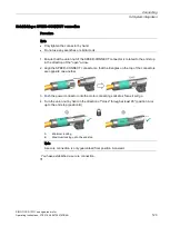
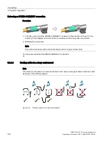
Page 124: ...sed away by the latches 2 Check that the two tabs are disengaged from the latches 3 Pull the connector out of the RJ45 socket of the Sensor Module You have now released the DRIVE CLiQ connection 5 4 4 3 Handling the quick action locking The motors are equipped with SPEED CONNECT connectors You can also connect quick connection cables with SPEED CONNECT to motor connectors as conventional cables wi...

Page 125: ...o the end stop in the direction of the open arrow 2 Align the SPEED CONNECT connector so that the triangles on the top of the connectors are opposite one another 3 Push the power connector onto the motor connecting socket as far as it will go 4 Turn the union nut by hand in the direction of close through at least 45 position A or up to the end stop position B A Minimum locking B Maximum locking up...

Page 126: ... stop The triangles on the top of the connectors must be opposite one another 2 Withdraw the connector Note Pull out the connector at the connector itself and do not pull on the cable You have disconnected the SPEED CONNECT connection 5 4 4 4 Routing cables in a damp environment Note If the motor is mounted in a humid environment the power and signal cables must be routed as shown in the following...

Page 127: ...tion is not overstressed When connected to IT line supplies a monitoring device must signal the first fault between an active part and ground Remove this fault immediately WARNING Danger to life caused by dangerous voltage while testing the insulation resistance During the measurement and immediately afterwards high voltages can be present at the terminals that can cause death or severe injury as ...

Page 128: ...TION Burns as a result of touching hot surfaces In operation the motor housing can reach high temperatures which can cause burns if touched Do not touch any hot surfaces Allow the motor to cool down before starting any work Use the appropriate personnel protection equipment e g gloves NOTICE Thermal damage to temperature sensitive parts Some parts of the electrical motor housing can reach temperat...

Page 129: ...the drive system according to the operating instructions of the converter being used Checklists prior to commissioning the 1FG1 servo geared motors Thoroughly familiarize yourself with the safety instructions and observe the checklists below before starting any work Table 6 1 Checklist 1 general checks Check OK Are all of the necessary components of the configured drive line up available correctly...

Page 130: ...ical system Check OK Have the minimum insulation resistance values been maintained Have the grounding and equipotential bonding connections been correctly established Is the maximum permissible input speed n1max maintained during operation on the converter Table 6 4 Checklist 4 Monitoring equipment checks Check OK Has it been ensured that speeds higher than the maximum permissible input speed of t...

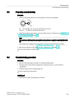
Page 131: ...and changing lubricants Page 145 Note For gearboxes with long term preservation and gearboxes supplied completely filled with oil We recommend a complete oil change after a storage time longer than 24 months 3 Mount an oil expansion unit See Mount the oil expansion unit Page 103 You have now prepared commissioning 6 4 Commissioning procedure Procedure Ensure that the frequency converter is correct...

Page 132: ...more information on this topic see the chapter in the Operating Instructions for the converter Switching on Precondition Ensure that the frequency converter is correctly parameterized Check whether sufficient heat is dissipated from the motor Procedure 1 Switch on the motor at the frequency converter 2 Observe any uneven running and abnormal noise of the motor 3 Check the function of the safety eq...

Page 133: ...n reach temperatures that exceed 100 C If temperature sensitive parts e g electric cables or electronic components come into contact with hot surfaces these parts could be damaged Ensure that no temperature sensitive parts are in contact with hot surfaces NOTICE Motor damage when the maximum speed is exceeded The maximum speed nmax is the highest permissible operating speed The maximum speed is sp...

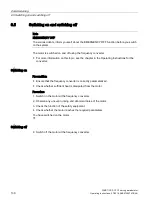
Page 134: ... Note EMERGENCY OFF To avoid accidents inform yourself about the EMERGENCY OFF function before you switch on the system The motor is switched on and off using the frequency converter For more information on this topic see the chapter in the Operating Instructions for the converter Switching on Precondition Ensure that the frequency converter is correctly parameterized Check whether sufficient heat...

Page 135: ...n damage the winding or bearings and could even destroy the system In case of uneven running or abnormal noise switch off the servo geared motor Identify the cause Check the gear unit during operation for Excessive operating temperature Changes in gear noise Possible leakage at the housing and shaft seals 7 4 Measures for longer non operational periods NOTICE Damage due to improper storage The mot...

Page 136: ...Operation 7 4 Measures for longer non operational periods SIMOTICS S 1FG1 servo geared motor 134 Operating Instructions 07 2019 A5E47360747B AA ...

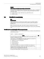
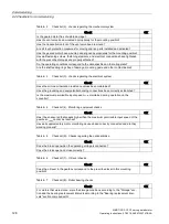
Page 137: ...ote Damage to the machine caused by faults Correct the cause of the fault as specified in the remedial measures section Repair any damage to the machine motor Note When operating the motor with a converter refer also to the operating instructions of the frequency converter if electrical faults occur If changes occur with respect to normal operation or faults determine the cause using the Possible ...

Page 138: ...anc es and insulation resistances repair after consultation with manufactur er C Interruption of a phase in the supply ca ble after switching on Check the converter and supply cables check the winding resistances D Converter output voltage too high fre quency too low Check the converter settings perform automatic motor identification F Winding short circuit or phase short circuit in stator winding...

Page 139: ...l the gearbox GK Overpressure due to lack of venting Mount the venting as appropriate for the mounting position Page 47 GL Overpressure due to soiled venting Replacing the vent valve Page 158 GM Shaft sealing rings defective Replace the shaft sealing rings GN Cover flange bolts loose Tighten the screws Page 144 Continue to monitor the gearbox GO Surface sealing defective e g on cover flange Reseal...

Page 140: ...Faults SIMOTICS S 1FG1 servo geared motor 138 Operating Instructions 07 2019 A5E47360747B AA ...

Page 141: ...ne from the power supply Switch off the machine Wait until the discharge time specified on the warning labels has elapsed Check that it really de energized from phase to phase and phase to protective conductor Check that every auxiliary circuit is de energized Ensure that the motors cannot move 3 Secure SIMOTICS motors against unintentional movements that generate a voltage at the terminals 4 Iden...

Page 142: ...ine is in operation can cause burns Do not touch frame parts while the machine is in operation or immediately after machine operation Allow frame parts to cool off before starting any work CAUTION Danger of scalding from the hot oil exiting the unit Exiting hot oil can cause burns Before starting any work wait until the oil has cooled down to below 30 C CAUTION Chemical burns and irritations cause...

Page 143: ...itional loads to the lifting equipment To hoist the motor use suitable cable guidance or spreading equipment particularly if the motor is equipped with built on assemblies The motor must not be lifted or transported by means of the power connector or signal connector Do not stand in the slewing range of hoisting gear or under suspended loads WARNING Danger to life through incorrect or unused lifti...

Page 144: ...mage to the machine Immediately perform an inspection when faults or exceptional conditions occur Maintenance measures inspection maintenance times intervals The maintenance intervals depend on the operating conditions Adapt the maintenance intervals to match the local conditions such as pollution dirt switching frequency load etc Perform the following maintenance measures as specified in the tabl...

Page 145: ...entative http www siemens com industr y contact if you detect any ab normalities Monthly Check the housing temperature Cooling of the servo geared motor Page 31 Check the gearbox for leaks Checking the gearbox for leaks Page 156 Every 3 000 operating hours or at least every 6 months Checking the oil level Checking the oil level Page 145 Check the oil quality Checking the oil quality Page 147 Clean...

Page 146: ...utput side Check the gearbox for leaks Page 156 1 When using synthetic oils the intervals can be doubled The data specified is valid for an oil temperature of 80 C For the oil change intervals for other temperatures see the figure titled Guide values for oil change intervals in chapter Service life of the lubricants Page 153 9 2 2 Thread sizes and tightening torques for fastening bolts The general...

Page 147: ...50 In the case of operating conditions listed by the operator the bearing service life for the bearings in the gearbox can be calculated with the help of the SIZER configuring tool If there are no specifications replace the bearings in the gearbox when you detect changes in the vibration and noise characteristics With medium loads replace the motor bearings the shaft sealing ring on the motor side...

Page 148: ...e mm mm Nm G 1 8 14 2 5 10 G 1 4 18 3 10 G 3 8 22 4 25 G 3 4 32 7 50 Procedure 1 Switch off the power supply to the converter 2 Unscrew the oil level plug Figure 9 2 Identifying marking for oil level plug Oil escapes if the maximum fill level is above the plug hole Note Use a suitable vessel to collect any escaping oil 3 Check the oil level in accordance with fill level x 4 Top up the oil level if...

Page 149: ... a specific product color Clouding or a flocculent appearance indicates water and or contamination A dark or black color indicates residue serious thermal decomposition or contamination Procedure 1 Allow the geared motor to run for a short time Wear and contaminant particles are visible in the oil shortly after shutting down 2 Switch off the power supply to the converter 3 Unscrew the vent plug or...

Page 150: ...remaining volume of used oil Change the oil completely If you use other oil types flush the gearbox with the new oil Avoid contaminating the new oil NOTICE Damage to the gearbox caused by incorrect oil quantities The incorrect oil quantity can damage the gearbox depending on the mounting position Install the geared motors only in the prescribed mounting position Regulate the oil level in accordanc...

Page 151: ... drain plug 4 Remove the oil drain plug Drain all the oil into the receptacle 5 Check the state of the sealing ring on the sealing element If the sealing ring is damaged replace the sealing element with a new one 6 After draining the oil seal the gearbox immediately using the sealing element You have now drained the oil from the gearbox Flushing the gearbox when changing between incompatible oils ...

Page 152: ...using a filter filter mesh max 25 μm For the flushing oil use the new oil or one that is compatible with the new oil and is less expensive 4 Operate the gearbox for 15 to 30 minutes under a low load 5 Place a suitable and sufficiently large receptacle underneath the oil drain plug 6 Remove the oil drain plug Drain all the oil into the receptacle Figure 9 7 Identifying marking for oil drain plug 7 ...

Page 153: ...red quantity of fresh oil Use a filler filter with mesh of max 25 μm Figure 9 9 Identifying marking oil filling inlet 3 Check the oil level Identifying marking for oil level plug Oil level in the oil sight glass 4 Top up the oil level if necessary and check it again 5 Check the state of the sealing ring on the sealing element If the sealing ring is damaged replace the sealing element with a new on...

Page 154: ...lubricant is shown on the rating plate The quality of the oil used must comply with the requirements laid down in the BA 7300 Operating Instructions otherwise the Siemens warranty is null and void We recommend the use of an approved gearbox lubricant specified in the T 7300 http support automation siemens com WW view de 44231658 Operating Instructions These oils have been tested appropriately and ...

Page 155: ...become shorter in the case of deviations from the permissible operating conditions e g high ambient temperatures high relative humidity and aggressive ambient media Contact Technical Support to determine the individual interval for changing the lubricant For a 80 C oil sump temperature the following service life can be expected when observing the properties specified by Siemens AG Table 9 4 Servic...

Page 156: ...e Under approved operating conditions and ambient temperatures no regreasing is required We recommend that the grease in the bearings is also renewed when the oil or shaft sealing rings are replaced 9 2 4 8 Recommended lubricants WARNING Used lubricants only have conditional approval The used lubricants are not or only conditionally approved for use in the foodstuff or pharmaceutical industry Use ...

Page 157: ...s Note The lubricants used are not at all or only conditionally biodegradable If biologically degradable lubricants are required use only gearbox lubricants with the appropriate classification listed in the T 7300 Operating Instructions Note These recommendations are not a guarantee of the lubricant quality provided by your supplier All lubricant manufacturers are responsible for the quality of th...

Page 158: ...n about oil quantities at DT Configurator http www siemens com dtconfigurator 9 2 5 Checking the gearbox for leaks Note From the inherent principle of operation oil mist can escape from the vent valve or a labyrinth seal Small quantities of oil or grease can escape at the shaft sealing ring during the run in period of 24 hours operating time If significant leaks occur or if a leak persists after t...

Page 159: ...un in period the shaft sealing ring beds into the shaft A visible track can be seen on the shaft Opti mum preconditions for a perfect seal are obtained after the run in period 9 2 6 Cleaning the gearbox NOTICE Damage to the gearbox due to increased housing temperatures resulting from dust deposits Dust deposits prevent heat dissipation increase the temperature of the gearbox housing and can cause ...

Page 160: ...e Center Bad Neustadt and other regional service sites throughout the world can handle or organize the maintenance repair of the servo geared motors Consult your regional Siemens contact person if you require this service 9 3 1 Replacing the vent valve To ensure fault free functioning renew the vent valve once a year When replacing prevent dirt and damaging atmospheres from entering the gearbox If...

Page 161: ...f the machine Wait until the discharge time specified on the warning labels has elapsed Check that it really de energized from phase to phase and phase to protective conductor Check that every auxiliary circuit is de energized Ensure that the motors cannot move 3 Secure SIMOTICS motors against unintentional movements that generate a voltage at the terminals 4 Identify all other dangerous energy so...

Page 162: ...tarting any work wait until the oil has cooled down to below 30 C CAUTION Chemical burns and irritations caused by chemical cleaning agents Chemical cleaning agents can be caustic or emit dangerous fumes If these come into contact with skin or if you inhale the fumes this can cause injuries e g chemical burns on the skin or respiratory passages or skin irritation During cleaning make sure that app...

Page 163: ...r ensure that it cannot roll CAUTION Injuries caused by liquids when draining and environmental pollution When draining liquids can cause injuries such as burns chemical burns irritation Spilt oil can make floor surfaces slippery and pollute the environment Allow the liquid to cool down Use a sufficiently large collection container Avoid liquids coming into contact with the skin Wear suitable pers...

Page 164: ...ure 1 Disconnect all electrical connections 2 Remove all liquids such as oil 3 Remove all supply lines 4 Remove the fixing elements from the geared motor 5 Transport the geared motor to a suitable location for storage and dismantling You have removed the motor 10 2 2 Dismantling the motor Note The rotor in a motor containing permanent magnets must only be removed by the manufacturer Contact the Si...

Page 165: ...SIMOTICS S 1FG1 servo geared motor Operating Instructions 07 2019 A5E47360747B AA 163 Appendix A A 1 Certificate for the PS Premium painting system from ECOLAB Figure A 1 Certificate_option_N16_page1 ...

Page 166: ...Appendix A 1 Certificate for the PS Premium painting system from ECOLAB SIMOTICS S 1FG1 servo geared motor 164 Operating Instructions 07 2019 A5E47360747B AA Figure A 2 Certificate_option_N16_page2 ...

Page 167: ... 2 ECOLAB cleaning recommendation SIMOTICS S 1FG1 servo geared motor Operating Instructions 07 2019 A5E47360747B AA 165 A 2 ECOLAB cleaning recommendation Figure A 3 ECOLAB cleaning recommendation for option N16 ...

Page 168: ......

Page 169: ...ty 21 UL and cUL 21 Circuit diagram 108 Commissioning 127 Cooling 31 Correct usage 20 D DRIVE CLiQ interface 113 F Faults 136 H Holding brake 31 Hotline 5 I Increased chemical resistance 39 Inspection and maintenance 139 M Maintenance intervals 142 N Noise emission 46 R Rating plate 28 RoHS 21 S Siemens Service Center 5 Sound pressure level 46 T Technical Support 5 Tightening torques 80 Training 5...

Page 170: ......
Reviews: