


Connecting
5.4 System integration
SIMOTICS S-1FG1 servo geared motor
Operating Instructions, 07/2019, A5E47360747B AA
111
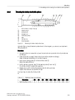
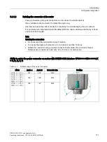
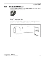
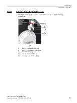
5.4.1.2
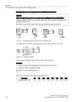
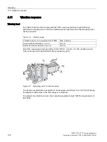
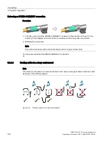
Rotating the connector at the motor
Power connectors and signal connectors can be rotated to a limited extent.
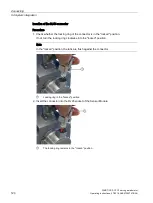
Use a suitable socket connector to rotate the angle plug.
Unscrew and open the socket connector completely to avoid damaging the pin contacts.
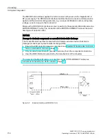
For encoders with integrated Sensor Modules (DQI) the cable outlet towards the top is fixed
and cannot be changed.
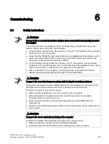
Note
Rotating the connectors
•
Do not exceed the permissible range of rotation.
•
To ensure the degree of protection, do not rotate more than 10 times.
•
Rotate the connector using a mating connector that matches the connector thread.
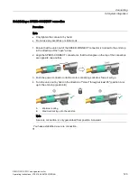
Rotate sensor modules by hand only. Use of tools is not permissible.
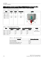
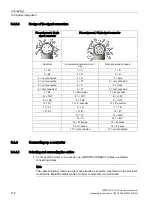
Ability to rotate the power connector on motors with DRIVE-
CLiQ interface 1FG1□□□
-
□□X□□
-
□□□□; X
= C, D, E, F, G
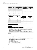
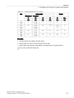
Table 5- 3
Rotation range of the power connector
Motor
Angle α
Angle β
Connector size
Drawing
1FG1□□□
-
□□C□□
122°
208°
M23
1FG1□□□
-
□□D□□
1FG1□□□
-
□□E□□
1FG1□□□
-
□□F□□
1FG1□□□
-
□□G□□
135°
195°
M23
1FG1□□□
-
□□F□□
1FG1□□□
-
□□G□□
195°
140°
M40
Summary of Contents for SIMOTICS S-1FG1
Page 1: ...SIMOTICS S 1FG1 servo geared motor ...
Page 2: ......
Page 140: ...Faults SIMOTICS S 1FG1 servo geared motor 138 Operating Instructions 07 2019 A5E47360747B AA ...
Page 168: ......
Page 170: ......


