

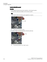


Connecting
5.4 System integration
SIMOTICS S-1FG1 servo geared motor
116
Operating Instructions, 07/2019, A5E47360747B AA
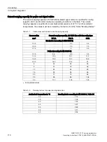
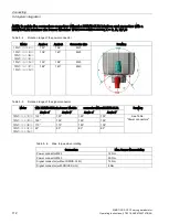
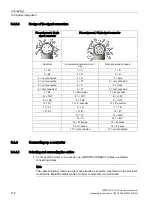
5.4.3.3
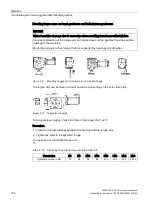
Design of the signal connectors
Pin assignment, 12-pin
signal connector
Pin assignment, 17-pin signal connector
Resolver
Incremental encoder sin/cos 1
Vpp
Absolute value encoders
1 = S2
1 = Α
1 = Α
2 = S4
2 = A*
2 = A*
3 = not connected
3 = R
3 = data
4 = not connected
4 = D*
4 = not connected
5 = not connected
5 = C
5 = clock
6 = not connected*
6 = C*
6 = not connected
7 = R2
7 = M encoder
7 = M encoder
8 = +1R1
8 = +1R1
8 = +1R1
9 = -1R2
9 = -1R2
9 = -1R2
10 = R1
10 = P encoder
10 = P encoder
11 = S1
11 = B
11 = B
12 = S3
12 = B*
12 = B*
13 = R*
13 = data*
14 = D
14 = clock*
15 = M sense
15 = M sense
16 = P sense
16 = P sense
17 = not connected
17 = not connected
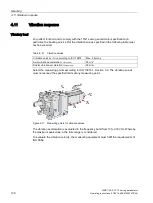
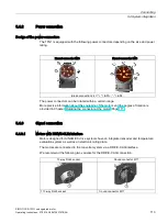
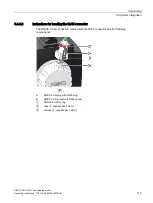
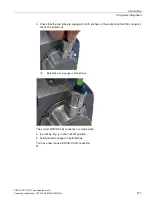
5.4.4
Connecting-up a converter
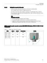
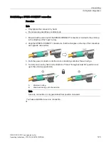
5.4.4.1
Selecting and connecting the cables
●
To connect the motor to a converter, use MOTION-CONNECT cables or shielded
connecting cables.
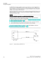
Note
The cable shielding, made up of as many strands as possible, must have a high electrical
conductivity. Braided shields made of copper or aluminum are well suited.
Summary of Contents for SIMOTICS S-1FG1
Page 1: ...SIMOTICS S 1FG1 servo geared motor ...
Page 2: ......
Page 140: ...Faults SIMOTICS S 1FG1 servo geared motor 138 Operating Instructions 07 2019 A5E47360747B AA ...
Page 168: ......
Page 170: ......


