


Motor components and options
4.1 Motor components
SIMOTICS M-1FE2 built-in motors
Configuration Manual, 05/2021, A5E50494252B AB
71
4.1.4
Commutation angle and pole position identification
4.1.4.1
Versions of pole position identification
Note
For the synchronous version, the commutation angle must be determined or entered when
the spindle is first commissioned or when the spindle is replaced.
The stator magnetic field must be aligned to the rotor magnetic field for the optimum torque
development (synchronized).
This reference is established using a pole position identification routine (PLI) and
subsequently passing over the encoder zero mark. The commutation angle offset that is
determined is saved to the drive system.
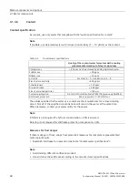
The pole position identification is available in two variants.
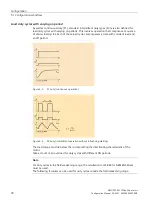
Motion-based pole position identification Induction-based pole position identifica-
tion
Precondition
The rotor must be able to freely rotate.
•
The rotor can rotate freely or be blocked
•
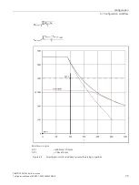
The pole position identification requires a
minimum current. The rated current (S1
current) of the motor module must be
≥
50% of the rated motor current.
Accuracy of determining the
rotor position.
High, independent of the magnetic proper-
ties
Dependent on the magnetic motor charac-
teristics
Effect of series reactors
Using series reactors has no effect on the
result.
Using series reactors or motors with low
saturation levels is not recommended, as
determining the rotor position is not precise
enough, or the pole position identification
does not provide any result.
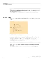
4.1.4.2
Determining the commutation angle (applies only to synchronous version)
The "installed" permanent magnetic field of the synchronous rotor must be synchronized with
the electrically generated magnetic field of the stator. This enables the two magnetic fields of
the stator and rotor to be optimally superimposed on one another.
This "synchronization angle" relative to the zero mark of the encoder system can be measured
and saved in the drive system (commutation angle offset).
Precondition
You are using the "STARTER" wizard for the commissioning.
Summary of Contents for SIMOTICS M-1FE2
Page 1: ......
Page 2: ......
Page 8: ...Introduction SIMOTICS M 1FE2 built in motors 6 Configuration Manual 05 2021 A5E50494252B AB ...
Page 161: ......
Page 162: ......


