


Connecting
8.2 Electrical connection
SIMOTICS M-1FE2 built-in motors
Configuration Manual, 05/2021, A5E50494252B AB
133
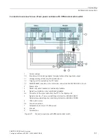
Preconditions for the switching in the terminal box
WARNING
Electric shock
Touching live components can result in death or severe injury.
•
Only work on electrical equipment if you are appropriately qualified.
•
Always observe the country-specific safety rules for all work.
•
Generally, the following six steps apply when establishing safety:
1.
Prepare for shutdown. Notify all those who will be affected by the procedure.
2.
Isolate the drive system from the power supply and take measures to prevent it being
switched back on again.
3.
Wait until the discharge time specified on the warning labels has elapsed.
4.
Check that there is no voltage between any of the power connections, or between them
and the protective conductor connection.
5.
Check whether the existing auxiliary supply circuits are de-energized.
6.
Ensure that the motors cannot move.
7.
Check that the correct drive system is completely locked.
After you have completed the work, perform the steps in the inverse sequence to restore
readiness for operation.
Make sure that the system is isolated from the power supply and protected against being
switched back on again.
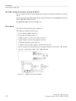
Procedure
1.
Open the terminal box.
2.
Undo the screws for the jumpers.
3.
Arrange the jumpers according to the required connection. (see diagram "Fixed star-delta
connection in the terminal box")
4.
Tighten the screws for the jumpers.
5.
Close the terminal box. Ensure that the gasket is in the correct position.
❒
Summary of Contents for SIMOTICS M-1FE2
Page 1: ......
Page 2: ......
Page 8: ...Introduction SIMOTICS M 1FE2 built in motors 6 Configuration Manual 05 2021 A5E50494252B AB ...
Page 161: ......
Page 162: ......


