


Connecting
8.2 Electrical connection
SIMOTICS M-1FE2 built-in motors
Configuration Manual, 05/2021, A5E50494252B AB
115
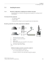
Guidelines for power connection
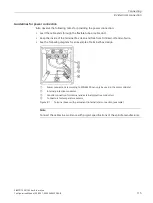
Also observe the following notes for providing the power connection:
•
Lead the cable ends through the flexible tube or cable duct.
•
Keep the inside of the terminal box clean and free from trimmed-off ends of wire.
•
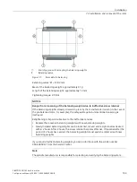
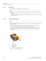
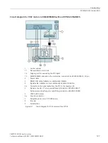
See the following diagram for an example of terminal box design
①
Power connections (according to DIN 46200 can only be used in the motor spindle)
②
Internal protective conductor
③
Ground connection for internal and external protective conductors
④
Connectors for temperature sensors
Figure 8-1
Terminal boxes with permanent (internal) star connection (example)
Note
Connect the cables in accordance with project specifications of the spindle manufacturer.
Summary of Contents for SIMOTICS M-1FE2
Page 1: ......
Page 2: ......
Page 8: ...Introduction SIMOTICS M 1FE2 built in motors 6 Configuration Manual 05 2021 A5E50494252B AB ...
Page 161: ......
Page 162: ......


