


Description
2.7 Selection and ordering data
SIMOTICS M-1FE2 built-in motors
Configuration Manual, 05/2021, A5E50494252B AB
39
2.7
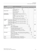
Selection and ordering data
The required Motor Modules are selected according to the peak and continuous currents that
occur in the load cycle.
If more than one motor is operated in parallel on one drive system, the total (summed) values
of the peak and continuous currents must be taken into account.
Use the SIZER (
https://support.industry.siemens.com/cs/document/54992004/sizer-for-
siemens-drives?dti=0&pnid=13434&lc=en-WW
) engineering tool to select the appropriate
Motor Module.
NOTICE
Damage to the insulation on synchronous built-in motors on regulated infeed units
Where synchronous built-in motors are used together with regulated (closed-loop
controlled) infeed units (e.g. Active Line Modules), electrical oscillations can occur with
respect to ground potential. These oscillations result in increased voltage loads (stress).
Factors that influence these system oscillations include, for example:
•
cable lengths
•
size of the Motor Module
•
number of axes
•
motor size
•
winding design
•
Avoid increased voltage loads or damage to the main insulation of the motor by using an
Active Interface Module in Active Line Mode of the motor.
Using smaller Motor Modules
Note
For several motor types, smaller Motor Modules with
I
n
<
I
n motor
can restrict the speed range
that can be used, even in partial load operation.
Therefore, please contact your local Siemens office.
Summary of Contents for SIMOTICS M-1FE2
Page 1: ......
Page 2: ......
Page 8: ...Introduction SIMOTICS M 1FE2 built in motors 6 Configuration Manual 05 2021 A5E50494252B AB ...
Page 161: ......
Page 162: ......


