


Connecting
8.2 Electrical connection
SIMOTICS M-1FE2 built-in motors
128
Configuration Manual, 05/2021, A5E50494252B AB
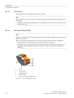
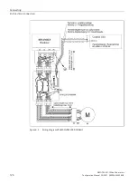
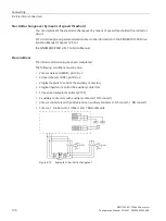
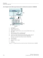
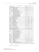
Circuit diagram for 1FE2 motor via SME120 with VPM to SINAMICS
1
Control cabinet
11
Voltage limiting (VPM), only if the EMF > 820 V
12
Not available in this circuit
13
SME120, encoder, motor side, connector kits 6FX2003-0SA12, 12-pin
2
Power cable
3
DRIVE-CLiQ cable, trailable or conditionally trailable
4
Signal cable, trailable or only conditionally trailable, Article No.
5
Signal connector, 17 pin, external thread, Article No.: 6FX2003-0SA17
Optional mounting flange for retrofitting, Article No.: 6FX2003-7DX00
6
1FE2 built-in motor
6a
Ground connection
7
Temperature sensor (+1 Pt1000 spare)
8
Encoder
9
Terminal box
Figure 8-8
Circuit diagram for 1FE2 motor with VPM via SME120
Summary of Contents for SIMOTICS M-1FE2
Page 1: ......
Page 2: ......
Page 8: ...Introduction SIMOTICS M 1FE2 built in motors 6 Configuration Manual 05 2021 A5E50494252B AB ...
Page 161: ......
Page 162: ......