


Connecting
8.2 Electrical connection
SIMOTICS M-1FE2 built-in motors
Configuration Manual, 05/2021, A5E50494252B AB
129
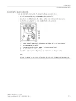
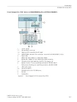
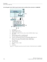
Overview of connections with two power units
You can operate the 1FE2 motor on two power units.
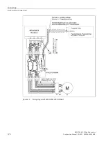
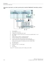
Connection overview for use of two power sections with the "SERVCOUP" OA software with VPM
Note
The following circuit applies only to 1FE2 with I
n
> 200 A for a parallel circuit on two booksize
Motor Modules.
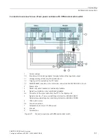
1
Control cabinet
11
Voltage limiting (VPM), only if the EMF > 820 V
12
Tripping unit for evaluating the PTC triplet
13
SMC20/SME20, encoder on the motor side, connector kits 6FX2003-0SA12, 12-pin
2
Power cable
3
DRIVE-CLiQ cable, trailable or conditionally trailable
4
Signal line, trailable or only conditionally trailable
4a
Conductor in the signal cable from the PTC to the tripping unit
5
Signal connector, 17 pin, external thread, Article No.: 6FX2003-0SA17
Optional mounting flange for retrofitting, Article No.: 6FX2003-7DX00
6
1FE2 built-in motor
6a
Ground connection
7
Temperature sensor (+1 Pt1000 spare)
8
Encoder
9
Terminal box
Figure 8-9
Connection overview with OA software and VPM
Summary of Contents for SIMOTICS M-1FE2
Page 1: ......
Page 2: ......
Page 8: ...Introduction SIMOTICS M 1FE2 built in motors 6 Configuration Manual 05 2021 A5E50494252B AB ...
Page 161: ......
Page 162: ......