Basics
3.19 Synchronous operation
S7-1500 Motion Control V13 Update 3
Function Manual, 07/2014, A5E03879256-AC
75
Synchronous motion
When a synchronous axis is synchronized to a master value, the "synchronous" status is
displayed by the parameter "MC_GearIn.InGear" = TRUE as well as in the tag of the
<TO>.StatusWord.X22 (Synchronous) technology object. The following axis follows the
dynamics of the leading axis according to the gear ratio.
The dynamic limits configured on the following axis are no longer in effect in the
"synchronous" state. The speed setpoint output to the drive is limited to the configured
maximum speed of the drive (<TO>.Actor.DriveParameter.MaxSpeed).
If the following axis cannot follow the master value, a following error occurs which is
monitored by the following error monitoring.
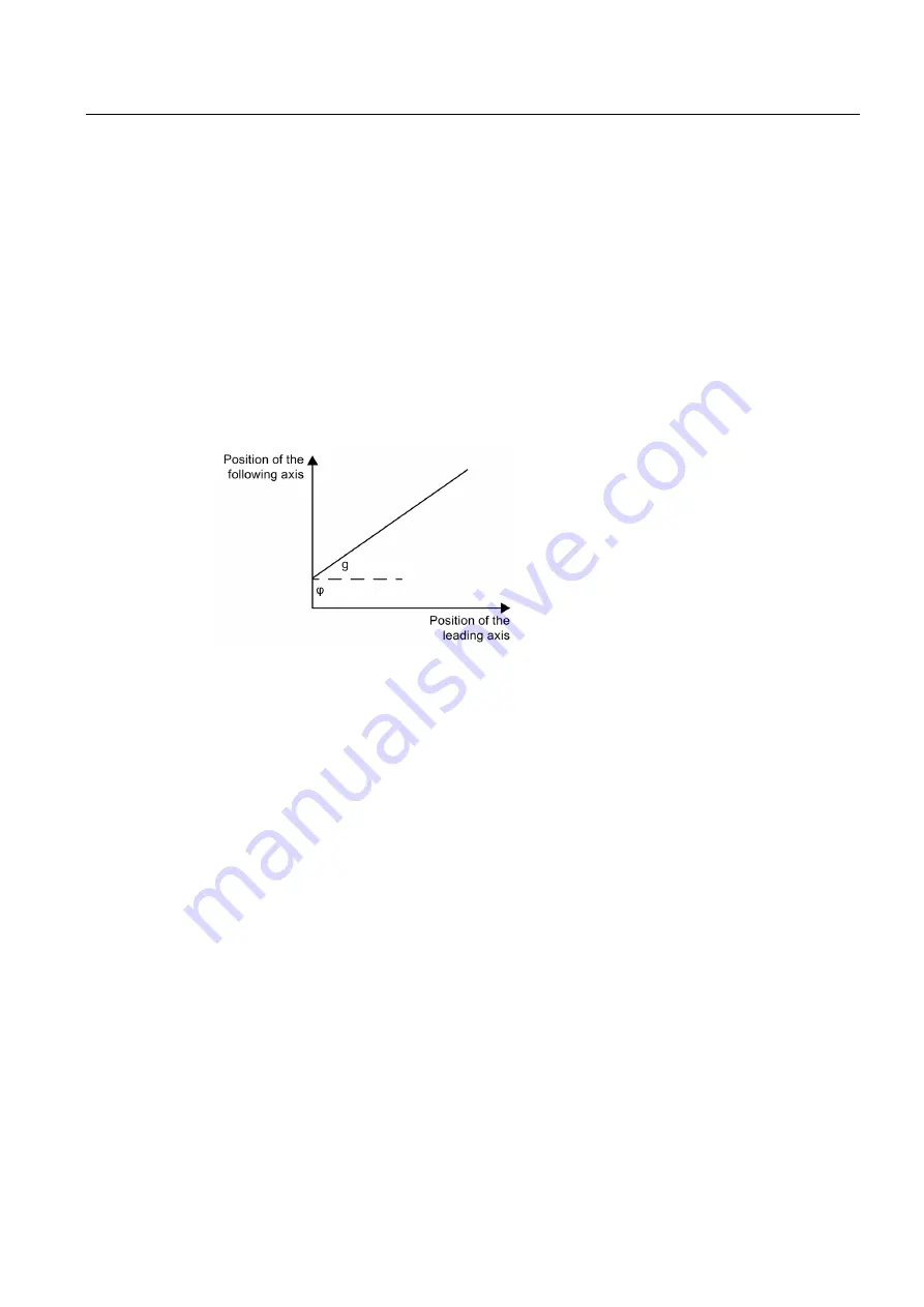
The response characteristic of gearing is expressed as a linear correlation between the
master value and the slave value.
g
Gear ratio (transformation ratio)
φ
Position offset between master value and slave value in synchronous operation
The position offset is derived from the synchronization and is constant thereafter.
The slave value is calculated according to the following formula:
Slave value = g × master value + φ
Overriding synchronous operation
An active synchronous operation is overridden by motion jobs on the following axis.
Direction
The numerator of the gear ratio is specified as positive or negative. This results in the
following response:
●
Positive gear ratio:
The leading and following axes move in the same direction.
●
Negative gear ratio:
The following axis rotates in the opposite direction of the leading axis.


