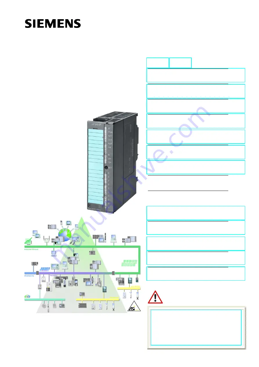
Summary of Contents for SIMATIC NET CP 343-2

Page 1: ...tes on the CE Mark C Glossary D Index Release 08 2008 C79000 G8976 C149 04 CP 343 2 CP 343 2 P AS Interface Master Manual SIMATIC NET The following supplements Edition 08 2010 belong to this documentation 1 Technical description 1 10 AS Interface operation with 24 V voltage AS i Power24V 5 Using the command interface 5 1 Description of FC ASI_3422 supplements 5 2 Description of the AS i slave comm...

Page 2: ...will result if proper precautions are not taken Warning indicates that death or severe personal injury can result if proper precautions are not taken Caution with warning triangle indicates that minor personal injury can result if proper precautions are not taken Caution without warning triangle indicates that damage to property can result if proper precautions are not taken Notice indicates that ...

Page 3: ...al description and only in connection with devices or components from other manufacturers which have been approved or recommended by Siemens This product can only function correctly and safely if it is transported stored set up and installed correctly and operated and maintained as recommended Before you use the supplied sample programs or programs you have written yourself make certain that no in...

Page 4: ...cannot guarantee full agreement However the data in this manual are reviewed regularly and any necessary corrections included in subsequent editions Suggestions for improvement are welcomed Disclaimer of Liability Copyright E Siemens AG 2001 2008 All rights reserved The reproduction transmission or use of this document or its contents is not permitted without express written authority Offenders wi...

Page 5: ...aves according to AS i Specification V3 For these CPs as of firmware version V3 0 configuration of the CTT slaves is supported as of STEP 7 version 5 4 SP4 The command interface has been expanded to allow the transfer of CTT2 strings The following AS i CPs do not support CTT slaves complying with AS i specification V3 S 6GK7 343 2AH00 0XA0 S 6GK7 343 2AH10 0XA0 As of STEP 7 version 5 3 SP3 the sel...

Page 6: ...ut connecting and operating the CP 343 2 in Chapter 1 2 and 3 You want to know how to operate the CP 343 2 from the PLC Read Chapter 4 Chapter 5 explains the command interface Requirements To understand this manual you require the following S Basic knowledge of SIMATIC S7 STEP 7 S Familiarity with the manual AS Interface Introduction and Basic Information on the accompanying product CD CD with sam...

Page 7: ...nings 25 2 2 Installing and Commissioning the CP 26 3 Configuration with STEP 7 28 3 1 General Information on Configuring the CP 343 2 with STEP 7 28 3 2 STEP 7 Basic Configuration 28 3 3 Extra Configuration of the CP 3 43 2 P 30 3 3 1 Configuring in STEP 7 Operating Parameters 30 3 3 2 Configuring AS i Slaves 31 3 4 Uploading the Actual Configuration to the PG CP 3 43 2 P only 38 4 Data Exchange ...

Page 8: ...figuration 69 5 2 9 Read_Extended_Actual_Configuration 70 5 2 10 Set_LPS 71 5 2 11 Set_Offline_Mode 72 5 2 12 Select Autoprogramming 73 5 2 13 Set_Operation_Mode 74 5 2 14 Change_AS I_Slave_Address 75 5 2 15 Get_AS i_Slave_Status 76 5 2 16 Get_LPS Get_LAS Get_LDS Get_Flags 77 5 2 17 Get_Extended_Total_Configuration 80 5 2 18 Store_Extended_Total_Configuration 85 5 2 19 Write_Extended_Parameter_Lis...

Page 9: ...ates 106 6 5 Local Data of the Diagnostic Organization Block OB82 106 6 6 Reading the Diagnostic Data Record DS 1 108 6 7 Programming Example 109 6 8 Diagnostic Interrupts Some Examples 110 7 Dealing with Problems Error Displays 11 7 1 Replacing a Defective AS i Slave Automatic Address Programming 111 7 2 Error Displays Remedying Errors 112 A AS Interface Protocol Implementation Conformance Statem...

Page 10: ...S Which options are available with the button configuration S How addressing is handled on the CPU Notice The two device types CP 343 2 and CP 343 2 P are largely identical in terms of functionality The CP 343 2 P however has additional options for configuration and parameter assignment during startup see Section 2 1 The CP 343 2 P module is not therefore intended as a replacement for the CP 343 2...

Page 11: ...tion on conditions for use in Chapter 2 Warning WARNING EXPLOSION HAZARD DO NOT DISCONNECT EQUIPMENT WHEN A FLAMMABLE OR COMBUSTIBLE ATMOSPHERE IS PRESENT Warning When used under hazardous conditions S If the cable or conduit entry point exceeds 70_C or the branching point of conductors exceeds 80_C special precautions must be taken If the equipment is operated in an air ambient of 50_C 60_C only ...

Page 12: ...n access the inputs and outputs on the AS i slaves from the PLC Depending on the slave type you can access binary values or analog values All AS i slaves complying with AS i specification V3 0 can be operated except for slaves complying with slave profile 7 1 and 7 2 Binary actuators sensors without Branch of the AS i cable AS i power supply unit Active module with slave ASIC Passive module withou...

Page 13: ...AS i power supply unit Active module with slave ASIC Passive module without slave ASIC AS i cable Binary sensors actuators with slave ASIC CP 343 2 slave ASIC Actuator sensor with direct connection ET 200M IM 153 PROFIBUS Figure 1 2 Distributed Use of the Master Module CP 343 2 in the ET 200M The CP 343 2 CP 343 2 P is not released for operation in the IM 153 3 ...

Page 14: ...343 2AH01 0XA0 CP 343 2 P Order number 6GK7 343 2AH11 0XA0 2 Backplane bus connector 3 Labeling strips 4 CD with sample programs and documentation The STEP 7 block FC ASI_3422 version 2 0 required for extended operation of the CP 343 2 is included on this CD Note The 20 pin front connector for attaching to the AS i cable is not supplied with the CP 343 2 You will find the order number of the front...

Page 15: ...cable Via S7 300 front connector with screw contacts 20 pin Current load between contact 17 and 19 and between 18 and 20 maximum 4 A Address area 16 I bytes and 16 Q bytes in the analog area of the S7 300 Current consumption from SIMATIC backplane bus Power supply SIMATIC backplane bus Current consumption from the AS i cable Power supply from the AS i cable max 200 mA 5 V DC max 100 mA DC 29 5 to ...

Page 16: ...dous locations ANSI ISA 12 12 01 CSA C22 2 No 213 M1987 CL 1 Div 2 GP A B C D T4 CL 1 Zone 2 GP IIC T4 CL 1 Zone 2 AEx nC IIC T4 FM FM 3611 CL 1 Div 2 GP A B C D T4 CL 1 Zone 2 GP IIC T4 Ta 0 60 C C TICK AS NZS 2064 Class A CE EN 61000 6 2 EN 61000 6 4 replaces EN 50081 2 ATEX Zone 2 EN 60079 15 2005 EN 60079 0 2006 II 3 G Ex nA II T4 KEMA 08 ATEX 0003X Note The current approvals are printed on th...

Page 17: ...8 7 6 5 4 3 2 1 0 Contacts 17 19 and 18 20 are jumpered internally on the CP 343 2 Figure 1 3 Front Connector Pin Assignment and Labeling on the CP 343 2 The CP 343 2 has internal contacts for two AS i cables that are jumpered internally on the CP This allows the CP 343 2 to be looped into the AS i cable Notice The load capacity of the contacts is a maximum of 4 A If this value is exceeded on the ...

Page 18: ...onfiguration Error This LED indicates whether the slave configuration detected on the AS i cable matches the configuration configured on the CP LPS If they do not match the CER LED is lit The CER LED is lit in the following situations S When a configured AS i slave does not exist on the AS i cable for example failure of the slave S When a slave exists on the AS i cable but it has not been configur...

Page 19: ...iguration data stored on the CP 343 2 match the values of existing AS i slaves SET Button The SET button is required for configuring the CP 343 2 in standard operation The button is only activated when the PLC is in the STOP mode If the CP 343 2 is in the configuration mode CM LED lit the CP 343 2 is configured automatically when the button is pressed Configuration involves the following steps 1 T...

Page 20: ... mode all activated AS i slaves are indicated by the LED being permanently lit Failed or existing but unconfigured AS i slaves are indicated by the corresponding LED flashing B B Example 1 Indicates that the slaves with addresses 1 2 and 5 are detected and activated Example 2 Indicates that the slaves with addresses 20 21 and 22 are detected and activated Figure 1 4 Examples of the Display of Dete...

Page 21: ...8976 C149 04 B B Example 3 Indicates that the slave with address 31B is detected and activated Example 4 Indicates that the slaves with addresses 10B and 17B are detected and activated Figure 1 5 Examples of the Display of Detected and Activated AS i Slaves on the Front Panel of the CP 343 2 ...

Page 22: ...volatile EEPROM At the same time the CP 343 2 is changed to the protected mode the CM LED goes off See Section 1 5 SET button The CER LED also goes off since following configuration the expected configuration stored on the CP 343 2 matches the actual configuration on the AS Interface Note Changing from the configuration mode to the protected mode is only possible when there is no AS i slave with a...

Page 23: ... in the cyclic data exchange Protected mode In protected mode the CP exchanges data only with the configured AS i slaves After configuring with the SET button activate protected mode by pressing the SET button again the CM LED goes off 1 8 Permitted Slots for the CP 343 2 in the SIMATIC S7 300 and in the ET 200M In principle the CP can be installed in all the slots for I O modules in the S7 300 an...

Page 24: ...t of the CP 343 2 Rack 0 Module PS CPU IM CP CP CP CP CP CP CP CP Slot number 1 2 3 4 5 6 7 8 9 10 11 Base address 1 2 3 256 272 288 304 320 336 352 368 Rack 1 Module IM CP CP CP CP CP CP CP CP Slot number 3 4 5 6 7 8 9 10 11 Base address 384 400 416 432 448 464 480 496 Rack 2 Module IM CP CP CP CP CP CP CP CP Slot number 3 4 5 6 7 8 9 10 11 Base address 512 528 544 560 576 592 608 624 Rack 3 Modu...

Page 25: ...omponents may impair suitability for Class I Division 2 or Zone 2 S This equipment is suitable for use in Class I Division 2 Groups A B C D Class I Zone 2 Group IIC or non hazardous locations Warning The device is designed for operation with safety extra low voltage SELV This means that only safety extra low voltages SELV complying with IEC950 EN60950 VDE0805 may be connected to the power supply t...

Page 26: ...ail in 4 when wiring between the power supply and the CPU 1 Install the CP on the S7 standard rail Slots 4 to 11 are permitted for the CP in racks 0 to 3 connected by IM 360 361 Proceed as in the sections dealing with setup and wiring described in detail in 1 2 Establish the connection via the enclosed bus connector to the backplane bus 3 Then secure the CP by the screws in its casing 4 Connect th...

Page 27: ...alue is exceeded on the AS i cable the CP must not be looped into the AS i cable but must be connected by a separate cable only one pair of CP terminals used Step Explanation Meaning 5 Turn on the power supply for the SIMATIC station and the AS i system 6 The remaining steps in commissioning involve downloading the configuration data For details on configuration refer to Section 1 6 and 3 ...

Page 28: ...he CP 343 2 P While configuration with the buttons as described in Section 1 6 simply allows querying of the current actual configuration by configuring in STEP 7 you can create a defined configuration regardless of the actual configuration and download it to the CP Note The information on the basic configuration in Section 3 2 applies both to the CP 343 2 and to the CP 343 2 P The information in ...

Page 29: ... 343 2 P To view general information addresses and operating parameters and to configure or modify them change to the Properties dialog of the CP 343 2 CP 343 2 P S General Tab Here you can change the name of the CP S Addresses Tab Reserved length S In the default setting 16 bytes are reserved Start addresses must be identical for inputs and outputs ...

Page 30: ...protected mode Automatic address programming if a slave is replaced If an AS i slave is replaced due to a fault the address is programmed automatically with the factory set ting address 0 for a replacement slave of the same type If this reaction is not desired for ex ample for safety reasons the op tion can be deselected here The settings you have made up to now in the Properties dialog are adequa...

Page 31: ...fic slave configuration select the Slave Configuration tab Double click on the row in the displayed table in which you want to enter an AS i slave with the corresponding address this opens the Properties dialog for AS i slaves Take the AS i slaves from the drop down list Three basic types of AS i slave are available S AS i A B Slave Universal AS i slave with extended addressing mode S AS i Standar...

Page 32: ...e relevant order number from the drop down list As an alternative you can open the slave selection dialog with the Selection button Here you will find the Siemens slaves with order numbers arranged according to groups Configuring the Properties of an AS i Slave By configuring the properties of the AS i slaves you can do the following S Enter configuration data of the AS i slaves S Specify the I O ...

Page 33: ...ailable in the B area 1 For AS i slaves that do not support the ID1 ID2 codes the values F hexadecimal must be entered As an option start up parameters can be permitted here Whether this parameter can be used depends on the slave type Enter the following vendor information for the AS i slaves in this area S I O configuration standardized meaning S ID code standardized meaning S ID1 2 code Extended...

Page 34: ...the I O configuration and the three ID codes Please refer to the operating instructions of the AS i slave you are using for information on the parameter settings These parameters are set in accordance with the DP standard V1 Example General I O configuration for analog slaves 1 For AS i slaves that do not support the ID1 ID2 codes the values FH must be entered ID codes for analog slaves as listed ...

Page 35: ... parameter can be used depends on the sla ve type Only 3 bits are available for A B slaves The 4th bit is required for the address switchover The parameters in this area specify the slave profile As well as the I O configuration S ID code standardized meaning S ID1 2 code Expanded ID code as of AS i Specification 2 1 AS i analog slaves with expanded address area If you use an analog slave with onl...

Page 36: ... analog values of these slaves using data records 140 to 147 Notice In the corresponding digital values STEP 7 does not indicate the correct number of bits Access to the user data by the user program is nevertheless always possi ble The following screenshot shows an example of the Slave Configuration tab in the Properties dialog of a module with configured CTT slaves Slave Configuration tab in the...

Page 37: ...bits irrelevant Data access using data record 140 147 Slave 4A CTT3 S 7 A 7 I2 4 I2 7 Q2 4 Q2 7 Slave 5A CTT3 S 7 A A All bits irrelevant Data access using data record 140 147 Slave 6A CTT4 S 7 A 8 Q3 6 I3 4 I3 7 Q3 4 Q3 5 Slave 7A CTT4 S 7 A 9 All bits irrelevant Data access using data record 140 147 Slave 8A 9A 10A 11A CTT5 S 6 0 x All bits irrelevant Data access using data record 140 147 Bit Q2...

Page 38: ...343 2 the configuration detected by the button configuration function is overwritten Follow the steps below Preparation Create the basic configuration and download to the station 1 Create a basic configuration by inserting the CP 343 2 P in an S7 300 station without AS i slaves in HW Config 2 Download this basic configuration to the S7 300 station using HW Config Uploading 3 Select the AS i Slave ...

Page 39: ...lues of the AS i analog slaves complying with profile 7 3 7 4 by reading or writing data records 140 147 For information on using the data record numbers with the CPU 318 refer to Restrictions in Section 1 1 4 1 Exchanging AS i Binary Values with Standard or A Slaves Interface between PLC CPU and CP 343 2 You can access the binary values of AS i standard slaves or A slaves in the user program usin...

Page 40: ...6 or 6A Slave 7 or 7A n 4 Slave 8 or 8A Slave 9 or 9A n 5 Slave 10 or 10A Slave 11 or 11A n 6 Slave 12 or 12A Slave 13 or 13A n 7 Slave 14 or 14A Slave 15 or 15A n 8 Slave 16 or 16A Slave 17 or 17A n 9 Slave 18 or 18A Slave 19 or 19A n 10 Slave 20 or 20A Slave 21 or 21A n 11 Slave 22 or 22A Slave 23 or 23A n 12 Slave 24 or 24A Slave 25 or 25A n 13 Slave 26 or 26A Slave 27 or 27A n 14 Slave 28 or 2...

Page 41: ...lave 4 slave 5 slave 30 slave 31 Bit 0 Bit 1 Bit 2 Bit 3 Bit 0 Bit 0 Bit 0 Bit 0 Bit 0 Bit 0 Bit 0 Bit 0 Bit 0 Bit 0 Bit 0 Bit 0 Bit 1 Bit 1 Bit 1 Bit 1 Bit 1 Bit 1 Bit 1 Bit 1 Bit 1 Bit 1 Bit 1 Bit 1 Bit 3 Bit 2 Bit 2 Bit 2 Bit 2 Bit 2 Bit 2 Bit 2 Bit 2 Bit 2 Bit 2 Bit 2 Bit 2 Bit 2 Bit 3 Bit 3 Bit 3 Bit 3 Bit 3 Bit 3 Bit 2 Bit 3 Bit 3 Bit 3 Bit 3 Bit 3 Bit 3 Bit 1 Bit 0 Bit 1 Bit 0 Output bytes ...

Page 42: ...the AS i slaves are accessed using S7 load and transfer commands such as L PIW X L PID X T PQW X T PQD X X stands for the byte address on the CP 342 2 Note The internal system allows access only to even byte addresses in words or double words The byte transfer commands L PIB X and T PQB X are not permitted in conjunction with the CP 342 2 Example Correct L PIW 260 Wrong T PQB 260 Wrong L PIW 257 ...

Page 43: ...PID 256 T DB20 DBD 0 L PID 260 T DB20 DBD 4 L PID 264 T DB20 DBD 8 L PID 268 T DB20 DBD 12 Examples binary access to standard A slaves A DB20 DBX 0 1 A DB20 DBX 3 0 DB20 DBX 47 3 Output binary output data of standard A slaves L DB20 DBD 32 T PQD 256 L DB20 DBD 36 T PQD 260 L DB20 DBD 40 T PQD 264 L DB20 DBD 44 T PQD 268 Slave 1 terminal 2 Slave 7 terminal 1 Slave 31 terminal 4 Note If you use a PL...

Page 44: ...slaves in the user program using the system function blocks SFC 58 SFC 59 write_data_record read_data_record For this function you always use data record number 150 PLC CPU AS i slave 2B AS i slave 1B AS i slave 31B ÍÍÍÍ ÍÍÍÍ ÍÍÍÍ ÎÎÎÎ ÎÎÎÎ ÎÎÎÎ Standard B slaves ÍÍÍ ÍÍÍ ÎÎÎ ÎÎÎ ÍÍÍ ÍÍÍ ÎÎÎ ÍÍÍ ÎÎÎ ÎÎÎ Backplane bus AS Interface CP 343 2 SFC 58 WR_REC DSNR 150 SFC 59 RD_REC DSNR 150 Data areas for...

Page 45: ...ucture of the binary data for the standard or A slaves Assignment I O byte number Bit 7 4 Bit 3 0 n 0 reserved Slave 1B Bit 3 Bit 2 Bit 1 Bit 0 n 1 Slave 2B Slave 3B n 2 Slave 4B Slave 5B n 3 Slave 6B Slave 7B n 4 Slave 8B Slave 9B n 5 Slave 10B Slave 11B n 6 Slave 12B Slave 13B n 7 Slave 14B Slave 15B n 8 Slave 16B Slave 17B n 9 Slave 18B Slave 19B n 10 Slave 20B Slave 21B n 11 Slave 22B Slave 23...

Page 46: ...L MW10 BUSY M9 0 RECORD P DB20 DBX16 0 Byte 16 Examples Binary access to B slaves A DBX 17 4 S DBX 49 6 A DBX 17 0 R DBX 49 6 Output binary output data of the B slaves CALL SFC 58 REQ TRUE IOID B 16 54 LADDR W 16 100 RECNUM B 16 96 RECORD P DB20 DBX48 0 Byte 16 RET_VAL MW12 BUSY M9 1 RD_REC Permanent trigger Fixed value CP address here 256 dec DSNR 150 binary data B slaves Dest area binary data Sl...

Page 47: ...t at F IN1 is closed S 2 and 3 0 if the contact at F IN2 is open S 2 and 3 1 if the contact at F IN2 is closed 4 4 Transferring AS i Analog Values Notice The following descriptions apply only to AS i slaves whose data is stored in the analog area Analog value transfer in compliance with AS i slave profile 7 1 7 2 is not supported by the CP 343 2 In this case analog value transfer must be imple men...

Page 48: ...uts Data records 140 147 for analog values inputs ÍÍÍÍ ÍÍÍÍ ÎÎÎÎ ÎÎÎÎ ÎÎÎÎ CP 343 2 Figure 4 4 4 4 1 Addressing Analog Values of AS i Slaves Mapping the Analog Values in the Data Records For each data record number you can use data record lengths between 2 bytes and max 128 bytes An 8 byte area is used for each slave address to address four analog channels Table 4 3 below shows which data record i...

Page 49: ...4 71 32 39 0 7 10 72 79 40 47 8 15 11 80 87 48 55 16 23 12 88 95 56 63 24 31 13 96 103 64 71 32 39 0 7 14 104 111 72 79 40 47 8 15 15 112 119 80 87 48 55 16 23 16 120 127 88 95 56 63 24 31 17 96 103 64 71 32 39 0 7 18 104 111 72 79 40 47 8 15 19 112 119 80 87 48 55 16 23 20 120 127 88 95 56 63 24 31 21 96 103 64 71 32 39 0 7 22 104 111 72 79 40 47 8 15 23 112 119 80 87 48 55 16 23 24 120 127 88 95...

Page 50: ...se data record 140 and specify 48 as the data record length 2 Configuration 1 analog slave with AS i address 7 is used You use data record 141 and specify 24 as the data record length 3 Configuration the entire address area for 31 analog slaves is used You use data record 140 and specify 128 as the data record length This covers analog slaves 1 16 For the other analog slaves 17 31 you use data rec...

Page 51: ... the analog slave The analog slave signals Value Invalid According to AS i Specification 3 0 these are slaves with the following profiles 6 0 A to 6 0 C 7 3 4 to 7 3 7 7 3 B to 7 3 F 7 4 1 to 7 4 F 7 A 9 7 A 8 ID1 6 7 A 8 ID1 7 7 A 5 and 7 5 5 and B A 5 S Transparent data In the input direction the AS i master returns the substitute value 0h when the analog slave supplies transparent data and when...

Page 52: ...ples processing analog values L DB20DBW 64 400 T DB20 DBW 88 T DB20 DBW 106 Output analog output data for slave 5 8 CALL SFC 58 REQ TRUE IOID B 16 54 LADDR W 16 100 RECNUM B 16 8D RECORD P DB20 DBX80 0 Byte 32 RET_VAL MW16 BUSY M9 3 RD_REC Permanent trigger Fixed value CP address here 256 dec DSNR 141 analog data slave 5 Dest area analog input data Slave 5 input channel 1 Slave 6 output channel 1 ...

Page 53: ...e write_record and read_record calls independently Points to Note S You will find FC ASI_3422 at the following locations In the STEP 7 block library SIMATIC_NET_CP as of STEP 7 V5 4 SP4 On the accompanying product CD S You must use version 2 0 or higher of the FC ASI_3422 S FC ASI_3422 must be interrupted during execution FC calls must not be programmed in priority classes that can interrupt each ...

Page 54: ...ser LADDR I WORD I Q M D L constant Base address of the CP 343 2 in the S7 address space The module base address is specified during STEP 7 configuration SEND I ANY I Q M D L Send buffer The parameter references a memory area in which the command must be specified by the user for example P DB20 DBX 20 0 byte 10 RECV I ANY I Q M D L Receive buffer This buffer is only relevant for commands that supp...

Page 55: ...buffer You transfer this response buffer with the RECV call parameter For status information the response buffer is not required for this FC interface 4 Activate the job with the parameter ACT 1 5 You then query the parameters DONE ERROR and STATUS For handling these parameters in the user program note the signal sequence of the parameters explained below The CD that ships with the CP contains sam...

Page 56: ...300 S7 400 modules for S7 400 S7 DP modules for S7 300 and S7 400 0 1 80A0H Negative acknowledgment when reading from AS i master 0 1 80A1H Negative acknowledgment when writing to AS i master 0 1 80A2H DP protocol error at Layer 2 0 1 80A3H DP protocol error involving user interface user 0 1 80A4H Communication problems on K bus 0 1 80B0H AS i master does not recognize the data record 0 1 80B1H Sp...

Page 57: ...ress 0 exists 0 1 83A3H An AS i slave with the new address already exists on the AS Interface 0 1 83A4H The AS i slave address cannot be deleted 0 1 83A5H The AS i slave address cannot be set 0 1 83A6H The AS i slave address cannot be stored permanently 0 1 83A7H Error reading the extended ID1 code 0 1 83A8H The target address is not plausible for example a B slave address was used for a standard ...

Page 58: ...indicates that a parameter is located in a write protected data block 0 1 8F32H The DB number in the parameter is too high 0 1 8F3AH The parameter contains the number of a DB that is not loaded 0 1 8F42H An access error has occurred while the system attempted to read out a parameter from the peripheral area of the inputs 0 1 8F43H An access error occurred while the system was attempting to write a...

Page 59: ... Slave address parameter Parameter echo optional 0 2 H Read_Parameter described in section 5 2 4 Slave address Parameter value 0 3 H Store_Actual_Parameters described in section 5 2 5 0 4 H Set_Extended_Permanent_Configuration described in section 5 2 6 Slave address Configuration data to be created 2 5 H Get_Extended_Permanent_Configuration described in section 5 2 7 Slave address Specified confi...

Page 60: ... described in section 5 2 23 Slave address ID code 1 7 H Read_AS i_Slave_Extended_ID1 described in section 5 2 24 Slave address Extended ID1 code 3 7 H Write_AS i_Slave_Extended_ID1 described in section 5 2 25 Extended ID1 code 3 F H Read_AS i_Slave_Extended_ID2 described in section 5 2 26 Slave address Extended ID2 code 3 8 H Read_AS i_Slave_I O described in section 5 2 27 Slave address I O confi...

Page 61: ... on a gray background Byte Meaning n 0 Response data n 1 Response data n Response data n base address of the response buffer on the DP master General Structure of the AS i Slave Address If an AS i slave is addressed in a command or in a response the address is structured as shown below Bit 7 Bit 6 Bit 5 Bit 4 Bit 0 S bit Slave address Where the S elect bit for selecting the slave type is specified...

Page 62: ...ng on the power supply on the CP 343 2 This call is not permitted for AS i slaves that comply with the AS i slave standard profile 7 4 For these AS i slaves the AS i master handles the AS i slave parameter assignment itself In this case the configured parameters are always set to FH Notice If you configure the AS i slaves with HW Config using the call described here is generally unnecessary If you...

Page 63: ...nent_Parameter Meaning With this call a slave specific parameter value stored on the EEPROM of the CP 343 2 is read Structure of the Job Data in the Send Buffer Byte Meaning 0 Command number 01 H 1 Slave address Structure of the Response Data in the Receive Buffer Byte Meaning Bit 7 Bit 4 Bit 3 Bit 0 0 0 configured parameters ...

Page 64: ...he response parameter echo This can deviate from the value that has just been written according to the AS i master specification 2 The AS i slave response is returned as a parameter echo in the response data This call is not permitted for AS i slaves that comply with the AS i slave standard profile 7 4 For these slaves the AS i master handles the AS i slave parameter assignment itself Structure of...

Page 65: ...actual parameter of an AS i slave sent by the CP 343 2 This value must not be confused with the parameter echo that is supplied by the AS i slave as a response to the write_parameter job Structure of the Job Data in the Send Buffer Byte Meaning 0 Command number 03 H 1 Slave address Structure of the Response Data in the Receive Buffer Byte Meaning Bit 7 Bit 4 Bit 3 Bit 0 0 0 Parameter ...

Page 66: ...rwritten with the current permanently stored actual parameters in other words the parameters of all the AS i slaves are configured For AS i slaves that comply with the AS i slave standard profile 7 4 the AS i master manages the AS i slave parameter assignment itself The configured parameters for these AS i slaves always have the value FH Structure of the Job Data in the Send Buffer Byte Meaning 0 ...

Page 67: ...on data is described in 2 If the addressed AS i slave does not support an extended ID code 1 2 the value FH must be specified When this command is executed the AS i master changes to the offline phase and then changes back to the normal mode warm restart on the AS i master This call is not made in the protected mode Notice If you configure the AS i slaves with HW Config using the call described he...

Page 68: ...f the AS i master S I O configuration S ID code S Extended ID1 code S Extended ID2 code The configuration data are specified by the manufacturer of the AS i slave The meaning of the configuration data is described in 2 Structure of the Job Data in the Send Buffer Byte Meaning 0 Command number 26H 1 Slave address Structure of the Response Data in the Receive Buffer Byte Meaning Bit 7 Bit 4 Bit 3 Bi...

Page 69: ... LAS is adopted in the list of permanent AS i slaves LPS When this command is executed the AS i master changes to the offline phase and then changes back to the normal mode warm restart on the AS i master The call is not executed in the protected mode Notice If you configure the AS i slaves with HW Config using the call described here is generally unnecessary If you do use the call you will overwr...

Page 70: ...terface are read S I O configuration S ID code S Extended ID1 code S Extended ID2 code The configuration data are specified by the manufacturer of the AS i slave The meaning of the configuration data is described in 2 Structure of the Job Data in the Send Buffer Byte Meaning 0 Command number 28 H 1 Slave address Structure of the Response Data in the Receive Buffer Byte Meaning Bit 7 Bit 4 Bit 3 Bi...

Page 71: ...figuration or the configuration set with HW Config Structure of the Job Data in the Send Buffer Byte Meaning Bit 7 Bit 6 Bit 5 Bit 4 Bit 3 Bit 2 Bit 1 Bit 0 0 Command number 29 H 1 00H 2 0 Slave 1 Slave 2 Slave 3 Slave 4 Slave 5 Slave 6 Slave 7 3 Slave 8 Slave 9 Slave 10 Slave 11 Slave 12 Slave 13 Slave 14 Slave 15 4 Slave 16 Slave 17 Slave 18 Slave 19 Slave 20 Slave 21 Slave 22 Slave 23 5 Slave 2...

Page 72: ...transfer was free of errors S This is followed by the inclusion phase in which there is a search for the existing AS i slaves and newly added AS i slaves are entered in the LDS or LAS S In the management phase jobs from the user such as writing parameters are executed In the offline mode the CP 343 2 only processes jobs from the user Jobs that involve the immediate addressing of an AS i slave are ...

Page 73: ...omatic address programming function see also Section 7 1 The AUTO_ADDR_ENABLE bit is stored permanently in other words it is retained after a warm hot restart on the AS i master Structure of the Job Data in the Send Buffer Byte Meaning Bit 7 Bit 1 Bit 0 0 Command number 0BH 1 0 Value for AUTO_ADDR_ENABLE 1 Automatic address program ming enabled 0 Automatic address program ming disabled ...

Page 74: ... i slaves except for AS i slave 0 are activated This also applies to AS i slaves in which there are differences between the expected and actual configuration The OPERATION MODE bit is stored permanently in other words it is retained following a cold warm restart When you change from the configuration mode to the protected mode there is a warm restart on the AS i master change to the offline phase ...

Page 75: ...ly be made when the following conditions are fulfilled 1 An AS i slave with AS i slave address old exists 2 If the old AS i slave address is not equal to 0 then an AS i slave with address 0 cannot be connected at the same time 3 The AS i slave address new must have a valid value 4 An AS i slave with AS i slave address new must not exist Note When the AS I slave address is changed the AS i slave is...

Page 76: ...parison recognizes that the stored address is not the same as the entry in the address register S 1 Parity error detected This flag is set when the AS i slave has recognized a parity error in a received frame since the last read and delete status job I O error detected An AS i slave can set this flag when it has detected and error for example wire break in the attached I Os S 2 End bit error detec...

Page 77: ...LAS slave 15 2 LAS slave 16 LAS slave 17 LAS slave 18 LAS slave 19 LAS slave 20 LAS slave 21 LAS slave 22 LAS slave 23 3 LAS slave 24 LAS slave 25 LAS slave 26 LAS slave 27 LAS slave 28 LAS slave 29 LAS slave 30 LAS slave 31 4 reserved LAS slave 1B LAS slave 2B LAS slave 3B LAS slave 4B LAS slave 5B LAS slave 6B LAS slave 7B 5 LAS slave 8B LAS slave 9B LAS slave 10B LAS slave 11B LAS slave 12B LAS...

Page 78: ... 7 17 LPS slave 8 LPS slave 9 LPS slave 10 LPS slave 11 LPS slave 12 LPS slave 13 LPS slave 14 LPS slave 15 18 LPS slave 16 LPS slave 17 LPS slave 18 LPS slave 19 LPS slave 20 LPS slave 21 LPS slave 22 LPS slave 23 19 LPS slave 24 LPS slave 25 LPS slave 26 LPS slave 27 LPS slave 28 LPS slave 29 LPS slave 30 LPS slave 31 20 reserved LPS slave 1B LPS slave 2B LPS slave 3B LPS slave 4B LPS slave 5B L...

Page 79: ...uted in other words exactly one AS i slave is currently out of operation AUTO_ADDR_ASSIGN This flag is set when the automatic address programming is possible in other words AUTO_ADDR_ENABLE 1 and there is no incorrect slave connected to the AS i Interface LDS_0 This flag is set when an AS i slave exists with address 0 CONFIG_OK This flag is set when the desired configured and actual configuration ...

Page 80: ... the expected configuration using the command Configure Total System see Section 5 2 18 Structure of the Job Data in the Send Buffer Byte Meaning 0 Command number 39H Structure of the Response Data in the Receive Buffer Byte Meaning Bit 7 Bit 6 Bit 5 Bit 4 Bit 3 Bit 2 Bit 1 Bit 0 0 00H 1 00H 2 reserved LAS slave 1 LAS slave 2 LAS slave 3 LAS slave 4 LAS slave 5 LAS slave 6 LAS slave 7 3 LAS slave ...

Page 81: ...7 25 Ext ID1 slave 7 Ext ID2 slave 7 26 ID_CODE slave 8 I O configuration slave 8 27 Ext ID1 slave 8 Ext ID2 slave 8 28 ID_CODE slave 9 I O configuration slave 9 29 Ext ID1 slave 9 Ext ID2 slave 9 30 ID_CODE slave 10 I O configuration slave 10 31 Ext ID1 slave 10 Ext ID2 slave 10 32 ID_CODE slave 11 I O configuration slave 11 33 Ext ID1 slave 11 Ext ID2 slave 11 34 ID_CODE slave 12 I O configurati...

Page 82: ...ID_CODE slave 1B I O configuration slave 1B 77 Ext ID1 slave 1B Ext ID2 slave 1B 78 ID_CODE slave 2B I O configuration slave 2B 79 Ext ID1 slave 2B Ext ID2 slave 2B 80 ID_CODE slave 3B I O configuration slave 3B 81 Ext ID1 slave 3B Ext ID2 slave 3B 82 ID_CODE slave 4B I O configuration slave 4B 83 Ext ID1 slave 4B Ext ID2 slave 4B 84 ID_CODE slave 5B I O configuration slave 5B 85 Ext ID1 slave 5B ...

Page 83: ...25 Ext ID1 slave 25B Ext ID2 slave 25B 126 ID_CODE slave 26B I O configuration slave 26B 127 Ext ID1 slave 26B Ext ID2 slave 26B 128 ID_CODE slave 27B I O configuration slave 27B 129 Ext ID1 slave 27B Ext ID2 slave 27B 130 ID_CODE slave 28B I O configuration slave 28B 131 Ext ID1 slave 28B Ext ID2 slave 28B 132 ID_CODE slave 29B I O configuration slave 29B 133 Ext ID1 slave 29B Ext ID2 slave 29B 1...

Page 84: ...meters slave 18B Parameters slave 19B 164 Parameters slave 20B Parameters slave 21B 165 Parameters slave 22B Parameters slave 23B 166 Parameters slave 24B Parameters slave 25B 167 Parameters slave 26B Parameters slave 27B 168 Parameters slave 28B Parameters slave 29B 169 Parameters slave 30B Parameters slave 31B 170 Flag 1 171 Flag 2 172 reserved 218 reserved Flag 1 Flag 2 Bit Number Meaning Bit N...

Page 85: ...s call is not executed in protected mode As of firmware version V3 0 the call is permitted both in protected and in configuration mode For AS i slaves that comply with the standard profile 7 4 the AS i master manages the parameter assignment itself The parameter values for slaves complying with standard profile 7 4 specified in the call are ignored by the AS i master Structure of the Job Data in t...

Page 86: ...7 25 Ext ID1 slave 7 Ext ID2 slave 7 26 ID_CODE slave 8 I O configuration slave 8 27 Ext ID1 slave 8 Ext ID2 slave 8 28 ID_CODE slave 9 I O configuration slave 9 29 Ext ID1 slave 9 Ext ID2 slave 9 30 ID_CODE slave 10 I O configuration slave 10 31 Ext ID1 slave 10 Ext ID2 slave 10 32 ID_CODE slave 11 I O configuration slave 11 33 Ext ID1 slave 11 Ext ID2 slave 11 34 ID_CODE slave 12 I O configurati...

Page 87: ...1B I O configuration slave 1B 77 Ext ID1 slave 1B Ext ID2 slave 1B 78 ID_CODE slave 2B I O configuration slave 2B 79 Ext ID1 slave 2B Ext ID2 slave 2B 80 ID_CODE slave 3B I O configuration slave 3B 81 Ext ID1 slave 3B Ext ID2 slave 3B 82 ID_CODE slave 4B I O configuration slave 4B 83 Ext ID1 slave 4B Ext ID2 slave 4B 84 ID_CODE slave 5B I O configuration slave 5B 85 Ext ID1 slave 5B Ext ID2 slave ...

Page 88: ...5B 125 Ext ID1 slave 25B Ext ID2 slave 25B 126 ID_CODE slave 26B I O configuration slave 26B 127 Ext ID1 slave 26B Ext ID2 slave 26B 128 ID_CODE slave 27B I O configuration slave 27B 129 Ext ID1 slave 27B Ext ID2 slave 27B 130 ID_CODE slave 28B I O configuration slave 28B 131 Ext ID1 slave 28B Ext ID2 slave 28B 132 ID_CODE slave 29B I O configuration slave 29B 133 Ext ID1 slave 29B Ext ID2 slave 2...

Page 89: ...ve 31B 170 Flag 1 171 Flag 2 Flag 1 Flag 2 Bit Number Meaning Bit Number Meaning 0 OFFLINE_READY 0 OFFLINE 1 APF 1 INTERNAL 2 NORMAL_MODE 2 EEPROM_OK 3 CONFIG_MODE 3 AUTO_ADDR_ENABLE 4 AUTO_ADDR_AVAIL 4 PERIPHERY_FAULT 5 AUTO_ADDR_ASSIGN 5 0 6 LDS_0 6 0 7 CONFIG_OK 7 MPO startup Flags whose values modify the AS i master mode are shown in gray The values of the other flags have no significance for ...

Page 90: ...10 Parameters slave 16 Parameters slave 17 11 Parameters slave 18 Parameters slave 19 12 Parameters slave 20 Parameters slave 21 13 Parameters slave 22 Parameters slave 23 14 Parameters slave 24 Parameters slave 25 15 Parameters slave 26 Parameters slave 27 16 Parameters slave 28 Parameters slave 29 17 Parameters slave 30 Parameters slave 31 18 irrelevant Parameters slave 1B 19 Parameters slave 2B...

Page 91: ...Par echo slave 14 Par echo slave 15 8 Par echo slave 16 Par echo slave 17 9 Par echo slave 18 Par echo slave 19 10 Par echo slave 20 Par echo slave 21 11 Par echo slave 22 Par echo slave 23 12 Par echo slave 24 Par echo slave 25 13 Par echo slave 26 Par echo slave 27 14 Par echo slave 28 Par echo slave 29 15 Par echo slave 30 Par echo slave 31 16 irrelevant Par echo slave 1B 17 Par echo slave 2B P...

Page 92: ... a CTT2 response The AS i master transfers this response as a byte string in the response buffer The strings are transferred by the AS i master with the response The structure of the CTT2 request or CTT2 response code index always begins with string byte 1 For more detailed information refer to the relevant AS i slave description As long as strings are being transferred on AS i there is no cyclic ...

Page 93: ...n_ID Meaning This call reads out the version ID of the firmware of the AS i master Structure of the Job Data in the Send Buffer Byte Meaning 0 Command number 14H The response of the AS i master contains the name and the firmware version number Structure of the Response Data in the Receive Buffer Byte Meaning 0 31 Version string ...

Page 94: ...ID code of an AS i slave can be read out directly over the AS i cable The call is intended for diagnostic purposes and is not required in the normal master mode Structure of the Job Data in the Send Buffer Byte Meaning 0 Command number 17H 1 Slave address Structure of the Response Data in the Receive Buffer Byte Meaning Bit 7 Bit 4 Bit 3 Bit 0 0 reserved ID code ...

Page 95: ...ded ID1 code of an AS i slave can be read out directly over the AS i cable The call is intended for diagnostic purposes and is not required in the normal master mode Structure of the Job Data in the Send Buffer Byte Meaning 0 Command number 37H 1 Slave address Structure of the Response Data in the Receive Buffer Byte Meaning Bit 7 Bit 4 Bit 3 Bit 0 0 reserved Extended ID1 code ...

Page 96: ... ID1 code of an AS i slave with address 0 can be written directly over the AS i cable The call is intended for diagnostic purposes and is not required in the normal master mode The AS i master passes on the extended ID1 code to the AS i slave without any plausibility check Structure of the Job Data in the Send Buffer Byte Meaning 0 Command number 3FH 1 irrelevant Extended ID1 code ...

Page 97: ...ded ID2 code of an AS i slave can be read out directly over the AS i cable The call is intended for diagnostic purposes and is not required in the normal master mode Structure of the Job Data in the Send Buffer Byte Meaning 0 Command number 38H 1 Slave address Structure of the Response Data in the Receive Buffer Byte Meaning Bit 7 Bit 4 Bit 3 Bit 0 0 reserved Extended ID2 code ...

Page 98: ...guration of an AS i slave can be read out directly over the AS i cable The call is intended for diagnostic purposes and is not required in the normal master mode Structure of the Job Data in the Send Buffer Byte Meaning 0 Command number 18 1 Slave address Structure of the Response Data in the Receive Buffer Byte Meaning Bit 7 Bit 4 Bit 3 Bit 0 0 reserved I O configuration ...

Page 99: ...it 4 Bit 3 Bit 2 Bit 1 Bit 0 0 Slave 0 Slave 1 Slave 2 Slave 3 Slave 4 Slave 5 Slave 6 Slave 7 1 Slave 8 Slave 9 Slave 10 Slave 11 Slave 12 Slave 13 Slave 14 Slave 15 2 Slave 16 Slave 17 Slave 18 Slave 19 Slave 20 Slave 21 Slave 22 Slave 23 3 Slave 24 Slave 25 Slave 26 Slave 27 Slave 28 Slave 29 Slave 30 Slave 31 4 Slave 0B Slave 1B Slave 2B Slave 3B Slave 4B Slave 5B Slave 6B Slave 7B 5 Slave 8B ...

Page 100: ...to the AS i master The actual number of parameter bytes to be sent to the AS i slave is calculated by the AS i master from byte 2 of the send buffer number of parameter bytes The remaining information in the string is not evaluated by the AS i master and is passed on to the AS i slave transparently As long as the string transfer is active there is no user analog data exchange with the addressed AS...

Page 101: ...he AS I master in byte 0 of the receive buffer number of parameter bytes If the AS i slave sends a string longer than 220 bytes the AS i master aborts the string transfer and terminates the job with an error The received data are then not made available to the user program As long as the string transfer is active there is no user analog data exchange with the addressed AS i slave Structure of the ...

Page 102: ...tes If the AS i slave sends a string longer than 220 bytes the AS i master aborts the string transfer and terminates the job with an error The received data are then not made available to the user program As long as the string transfer is active there is no user analog data exchange with the addressed AS i slave Note As an exception with this call the bytes contained in the bits Follows and Valid ...

Page 103: ...the AS i master in byte 0 of the receive buffer number of diagnostic bytes If the AS i slave sends a string longer than 220 bytes the AS i master aborts the string transfer and terminates the job with an error The received data are then not made available to the user program As long as the string transfer is active there is no user analog data exchange with the addressed AS i slave Structure of th...

Page 104: ... S If the user has programmed OB 82 this is started by the PLC operating system The local data of OB 82 already provides the user with a certain amount of diagnostic information Which module triggered the interrupt What type of error has occurred The user program can obtain more detailed information which slave has failed by reading the diagnostic data record DS 1 using the system functions SFC 51...

Page 105: ...a of OB82 It is possible but not necessary to read DS 1 that contains the delta list in OB82 using an SFC call SFC 51 RDSYSST or SFC 59 RD_REC When OB has been executed the PLC CPU acknowledges the diagnostic interrupt on the CP 342 2 If interrupt events occur in a status in which they cannot be signaled by triggering a diagnostic interrupt for example when the PLC is in the STOP mode or when an o...

Page 106: ...e STOP mode a diagnostic interrupt is generated at the next possible time only if the problem still exists 6 5 Local Data of the Diagnostic Organization Block OB82 The following table shows the DS 0 available in the local data of OB82 local byte 8 to local byte 11 For the meaning of the other OB82 local data please refer to the STEP 7 descriptions Byte Bit Variable Name Data Type Meaning 8 20 OB82...

Page 107: ...2 is in the normal state 1 CP 343 2 is in the offline state 10 23 OB82_WTCH_DOG_FLT BOOL Hardware error on the CP internal watchdog 10 24 OB82_INT_PS_FLT BOOL with the CP 343 2 always 0 10 25 OB82_PRIM_BATT_FLT BOOL with the CP 343 2 always 0 10 26 OB82_BCKUP_BATT_FLT BOOL with the CP 343 2 always 0 10 27 OB82_RESERVED_2 BOOL with the CP 343 2 always 0 11 20 OB82_RACK_FLT BOOL with the CP 343 2 al...

Page 108: ...ze the time at which DS1 is read it is advisable to use SFC 51 On the CP 343 2 DS 1 always has a length of 16 bytes and is structured as follows Byte Value meaning 0 3 These four bytes contain DS 0 and correspond to the local data bytes 8 to 11 in OB82 Byte Value Purpose 4 60H Fixed value 5 00H Fixed value 6 40H Fixed value Byte Bit Value meaning 7 0 7 1 error in AS i slave 0 7 8 0 7 1 error in AS...

Page 109: ... 20 0 temp t_header Struct 0 0 temp len WORD 2 0 temp nr WORD 4 0 temp END_STRUCT OB82 Code L 256 L OB82_MDL_ADDR I BEC CALL RDSYSST REQ TRUE SZL_ID W 16 B3 INDEX W 16 100 RET_VAL MW18 BUSY M9 4 SZL_HEADER t_header DR P M 100 0 Byte 16 Example of an error reaction 0 M107 1 0 M107 7 0 M111 3 M9 5 No relevance for the CP 343 2 Address of the CP 343 2 Interrupt from the CP 343 2 DS1 via logical base ...

Page 110: ...formation MD 107 80 00 00 00H MD 111 00 00 00 00H If the unconfigured slave 15 is then connected to the AS interface the CP 343 2 generates another diagnostic interrupt The module fault message appears in the system diagnostic buffer again The delta list then changes to the following value MD 107 80 80 00 00H MD 111 00 00 00 00H After reconnecting slave 7 to the AS interface there is still an erro...

Page 111: ...ddress slaves do not support automatic address programming The sections below explain how to replace failed AS i slaves using the automatic address programming function Detecting a Defective AS i Slave If the AUP LED is lit only in the protected mode this indicates the following S Exactly one slave has failed S Automatic address programming by the CP 343 2 is possible You can recognize the failed ...

Page 112: ...S i configuration error has occurred for example slave failure Eliminate the configuration error The CP is defective Internal EEPROM error see signaling S7 300 system diagnostic buffer Replace the CP SF is lit when the SET button is pressed A slave with address 0 exists when there is a change to the pro tected mode Remove the slave with address 0 from the AS i cable CER LED is permanently lit The ...

Page 113: ...ton for at least 0 5 seconds After failure of an AS i slave the AUP display remains off The CP 343 2 is in the configura tion mode Automatic Programming is not possible in the configuration mode Program the address of the new AS i slave with the address pro grammer or using the command interface of the CP 343 2 More than one AS i slave has fai led Check the AS i cable If APF is displayed at the sa...

Page 114: ...ssible Cause The replaced AS i slave is not cor rectly connected or is defective Check the connections of the slave and if necessary replace the slave The CER LED and the LEDs of active AS i slaves flicker irregu larly An extender is installed in the AS interface with Line1 and Line2 and the connections are reversed Correct the connections on the extender ...

Page 115: ...does not exist Table K 2 PICS No Function or Call on the Host Interface symbolic representation M4 Comment Function implemented by 1 Image Status Read_IDI X By the PLC accessing the I O data of the CP 343 2 or with data record DS 150 for B slaves 2 Status Write_ODI Image X By the PLC accessing the I O data of the CP 342 2 or with data record DS 150 for B slaves 3 Status Set_Permanent_Parameter Add...

Page 116: ...X see Section 5 2 16 0 Status Get_Flags X see Section 5 2 16 1 Status Flag Get_Flag_Config_OK X see Section 5 2 16 2 Status Flag Get_Flag_LDS 0 X see Section 5 2 16 3 Status Flag Get_Flag_Auto_Address_Assign X see Section 5 2 16 4 Status Flag Get_Flag_Auto_Prog_Available X see Section 5 2 16 5 Status Flag Get_Flag_Configuration_Active X see Section 5 2 16 6 Status Flag Get_Flag_Normal_Operation_Ac...

Page 117: ...IDCOD1 X see Section 5 2 22 7 Status Resp Cmd_Read_Ext_ID Code_2 Addr IDCOD2 X see Section 5 2 23 Status S_List Get_LPF X see Section 5 2 24 Status Write_Extended_ID Code_11 S_Ext_ID Co de_1 X see Section 5 2 25 AImage Status Read_AIDI X not implemented 26 Status Write_AODI AImage X not implemented 27 String Status Read_ParamStr S_Addr X not implemented 28 Status Write_ParamStr S_Addr String X not...

Page 118: ...of connected slaves The AS i cycle time can be calculated using the following formula If 5 or more AS i slaves are activated tcycl 1 number of activated AS i slaves x 154 ms If less than 5 AS i slaves are activated tcycl 1 number of activated AS i slaves x 654 ms Note If two 2 AS i slaves with extended addressing mode occupy the same address for example address 5A and address 5B this slave pair is...

Page 119: ...any Tel 49 6051 473212 Fax 49 6051 473282 E Mail info as interface net The AS i technology is promoted by the AS Interface Association Internet address of the AS International Association http www as interface net 3 SIMATIC NET Industrielle Kommunikation für Automation and Drives Catalog IK PI The catalog can be ordered from your local SIEMENS branch office or distributor 4 SIMATIC S7 S7 300 Autom...

Page 120: ...logs and obtain additional information from your local SIEMENS branch or distributor You will find many of the Siemens AG manuals on the Internet pages of Siemens Customer Support for automation http support automation siemens com Enter the ID of the manual in the search box The ID is shown in parentheses in the literature references You can locate manuals included in the online documentation of t...

Page 121: ...ach 4848 D 90327 Nürnberg Germany Area of Application The product meets the following requirements Area of application Requirements Emission Immunity Industrial area EN 61000 6 4 2007 EN 61000 6 2 2005 If the product is used in a domestic area it may interfere with other devices Installation Instructions The product meets the requirements if you adhere to the installation instructions in Chapter 2...

Page 122: ...s and actuators with the controllers previously known as SINEC S1 AS i A B slave AS i A B slaves use the extended addressing mode Pairs of A B slaves can be assigned to one address on the AS Interface by organizing addresses in this way up to 62 AS i A B slaves can be attached to the AS Interface AS i analog slave AS i analog slaves are special AS i standard slaves that exchange analog values with...

Page 123: ...ted AS i attachment and their address range AS i standard slaves and AS i A B slaves with the extended addressing mode AS i standard slave An AS i standard slave always occupies one address on the AS Interface with this address organization up to 31 AS i standard slaves can be attached to the AS Interface APF AS i Power Fail Flag or LED display that indicates that the power supply on the AS i cabl...

Page 124: ...AS List of activated slaves LDS List of detected slaves LPS List of permanent slaves Nibble A nibble is a unit of information consisting of four bits Standard AS i master Up to 31 standard slaves or slaves with the extended addressing mode A slaves only can be attached to a standard AS i master ...

Page 125: ...9 Configuration mode 19 22 23 Configuration with S7 300 ET 200M 12 13 Configuring Button configuration 22 Configuring in STEP 7 28 CTT slaves 36 D Diagnostic data record DS1 108 Diagnostic interrupt processing sequence 105 Diagnostic OB OB82 106 Download to project 38 DP slave configuring properties 29 E Error coding 56 Error displays 112 remedies 112 ESD guidelines 11 Examples binary analog value...

Page 126: ...126 CP 343 2 CP 343 2 P AS Interface Master Release 08 2008 C79000 G8976 C149 04 T Technical specifications 15 U Upload to PG 38 User program 55 ...

Page 127: ... Supplement to manual AS Interface Master CP 343 2 CP 343 2 P for SIMATIC S7 Operating Manual 08 2010 A5E03006584020A 01 Technical description 1 Using the command interface 5 Dealing with problems error displays 7 ...

Page 128: ...t documentation for the specific task in particular its warning notices and safety instructions Qualified personnel are those who based on their training and experience are capable of identifying risks and avoiding potential hazards when working with these products systems Proper use of Siemens products Note the following WARNING Siemens products may only be used for the applications described in ...

Page 129: ...quest command number 44H 10 5 2 30 Read_AS i slave_parameter_string command number 41H 10 5 2 31 Read_AS i slave_ID string command number 42H 10 5 2 32 Read_AS i slave_diagnostic_string command number 43H 10 7 Dealing with problems error displays 11 7 1 Replacing a defective AS i slave automatic address programming 11 7 1 1 Automatic address programming after failure of one or more AS i slaves CP ...

Page 130: ...CP 343 2 CP 343 2 P AS Interface Master for SIMATIC S7 4 Supplement to Operating Manual 08 2010 A5E03006584020A 01 ...

Page 131: ...order to limit the voltage drop on the AS Interface cable the maximum permissible cable length specified for a 24 V DC supply voltage is 50 m The extension plug cannot be used to extend the cable length The AS Interface method of communication is identical for both 30 V and 24 V supply voltages The possible number of addresses and slaves on the AS Interface network is therefore unaffected by the s...

Page 132: ... the delivery state and the CP 343 2 CP 343 2 P module is thus preset for operation on a 30 V supply voltage Checking the setting of voltage monitoring only on 6GK7 343 2AH01 0XA0 and 6GK7 343 2AH11 0XA0 product version 02 Step Meaning 1 Install the CP as described in Section 2 2 2 Switch the power supply to the SIMATIC station off and then on again The CP performs a self test when it powers up Al...

Page 133: ...the LEDs then display the operating state described in Section 1 5 4 Press and hold down the SET button for at least 5 s until the LED APF flashes Note This action is only possible within 30 s of switching on the SIMATIC station Pushbutton actuation detected The device is in setting mode 5 Release the SET button The LED APF flashes Voltage monitoring status display LED 1 lights up Voltage monitori...

Page 134: ...running light display is activated LED SF PWR APF CER AUP CM The CP cannot operate normally in this special state To cancel this special state the power supply to the SIMATIC station must be switched off NOTICE Note on step 7 storing the setting If you want to cancel the setting of the voltage monitoring without saving it you must switch off the power supply to the SIMATIC station instead of perfo...

Page 135: ...ASI_3422 supplements CAUTION If the receive buffer of the FC ASI_3422 is too short any bordering memory areas are overwritten The length specification in the ANY pointer of the parameter RECV when calling the FC ASI_3422 is irrelevant The required length of the receive buffer can be found in the description of the command The supplements listed below must be observed ...

Page 136: ...i master with zero values 5 2 30 Read_AS i slave_parameter_string command number 41H Supplement The receive buffer must have a length of 221 bytes byte 0 to 220 The number of bytes actually transferred by the AS i slave depends on the slave The additional bytes contained in the receive buffer may be overwritten by the AS i master with zero values 5 2 31 Read_AS i slave_ID string command number 42H...

Page 137: ...s have failed If several AS i slaves have failed the defective slaves must be uniquely identified in the configuration by their slave profile I O configuration ID code ID2 code and ID1 code The automatic address programming function does not work if two identical slaves have failed The automatic address programming function also supports slaves with the CTT5 profile multi address slaves and AS i d...

Page 138: ...matic address programming by the CP 343 2 is possible You can identify a failed AS i slave by flashing of the LED assigned to the slave on the front plate The corresponding LEDs flash to indicate failure of a device with more than one internal slave address Replacement of a defective AS i slave Replace the defective AS i slave by an identical AS i slave with address zero setting in delivery state ...

Page 139: ...tion only if the CP 343 2 is operating in protected mode and only one AS i slave has failed Slaves with the CTT5 profile multi address slaves do not support automatic address programming Detection of a defective AS i slave An illuminated AUP LED signals the following in protected operation only Exactly one slave has failed Automatic address programming by the CP 343 2 is possible You can identify ...

Page 140: ...he slave specification is equal to or lower than the version of the master specification Examples of incompatible combinations of AS i slaves and AS i master list not complete Slave of type A B including A B slave with 4 inputs 3 outputs e g 3RK2400 1FQ03 0AA3 in accordance with AS i spec V2 1 on master 6GK7342 2AH00 0XA0 in accordance with AS i spec V2 0 especially if the highest output bit of th...

Reviews: