


Change History
Sicore II Installation and Commissioning Guide
667/HB/52600/000 Issue 2 Unrestricted
8
Change History
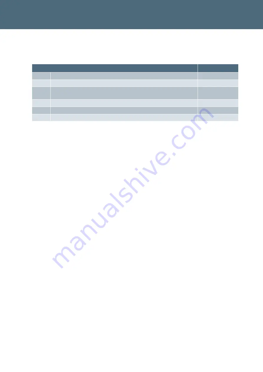
Change History
Issue
Change Reference
Date
1
Formal Issue
Nov 2017
2
Added Security Recommendations (Section 2), Appendix B and
Appendix C
Jan 2018
Table 1 – Change History