7SG11 Argus 6 Diagrams and Parameters
©2013 Siemens Protection Devices Limited
P20011 Page 9 of 22
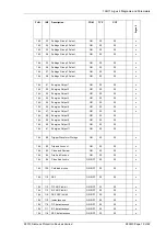
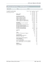
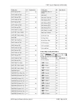
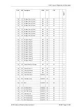
Setting name
Ref Applied
value
Gn
R
E/F Charact.
2.3.1
Gn[
F
] E/F Lowset
2.3.2
Gn
R
E/F Lowset
2.3.2
Gn[
F
] E/F Highset1
2.3.2
Gn
R
E/F Highset1
2.3.2
Gn[
F
] E/F Highset2
2.3.2
Gn
R
E/F Highset2
2.3.2
Gn [SEF/REF] Starter
2.4
Gn [SEF/REF] Delay1
2.4
Gn [SEF/REF] Delay2
2.4
Gn [SEF/REF] Lowset
2.4
Gn P/F FWD Block
2.7
Gn P/F REV Block
2.7
Gn E/F FWD Block
2.7
Gn E/F REV Block
2.7
Gn Status 1
2.11
Gn Status 2
2.11
Gn Status 3
2.11
Gn Status 4
2.11
Gn Status 5
2.11
Gn Status 6
2.11
Gn Status 7
2.11
Gn Status 8
2.11
Gn Status 9
2.11
Gn CB Fail 1
2.5
Gn CB Fail 2
2.5
Gn Trip Alarm
2.14.1
Gn Counter Alarm
2.14.1
Gn FOC Alarm
2.14.1
Gn I² Alarm
2.14.1
Gn Power On Count
2.14.3
Gn Hand Reset
2.11
Gn Pulsed Relays
2.11
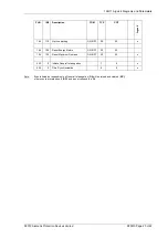
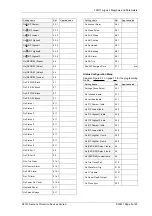
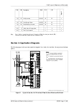
Setting name
Ref Applied
value
Gn Lockout Alarm
2.9.1
Gn Close Pulse
2.9.1
Gn AUX Close
2.9.1
Gn ARC Active
2.9.1
Gn Reclaimed
2.9.1
Gn SA Blocked
2.9.1
Gn SA Alarm
2.9.1
Gn SA Trip
2.9.1
Min O/P Energise Time
2.11
ms
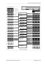
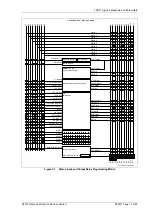
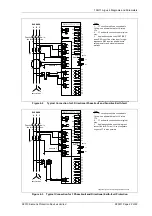
Status Configuration Menu
See also Figure 2-1 on page 13 for the programming
matrix.
Setting name
Ref Applied
value
Settings Group Select
2.2.1
Gn Inverted Inputs
2.11
Gn Latched Inputs
2.11
Gn P/F Charact. Inhib.
2.3.1
Gn P/F Lowset Inhib.
2.3.2
Gn P/F Highset 1 Inhib.
2.3.2
Gn P/F Highset 2 Inhib.
2.3.2
Gn E/F Charact. Inhib.
2.3.1
Gn E/F Lowset Inhib.
2.3.2
Gn E/F HighSet 1 Inhib.
2.3.2
Gn E/F HighSet 2 Inhib.
2.3.2
Gn [SEF/REF] Delay 1 Inhib.
2.4
Gn [SEF/REF] Delay 2 Inhib.
2.4
Gn [SEF/REF] Lowset Inhib.
2.4
Gn Trip Circuit Fail
2.10
Gn Waveform Trig
2.13.3
Gn I
2
Update
2.14.1
Gn Reset Flag & Output
2.11
Gn Clock Sync.
2.2.7


