7SG11 Argus User Manual
©2013 Siemens Protection Devices Limited
P20006 Page 9 of 37
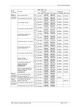
Available Instruments
Primary current – RMS values on a phase-by-phase basis, indicated by upper case letters, e.g. A, B, C, E, SE
(sensitive earth)
Secondary current – RMS values on a phase-by-phase basis, indicated by lower case letters, e.g. a, b, c, e,
se
Primary phase voltages *
Primary phase-phase voltages *
Secondary voltages *
Apparent power and power factor *
Real and reactive power *
WHr forward and reverse *
VarHr forward and reverse *
Rolling and Max demand Ia, Ib, Ic
Rolling and Max demand W*
Rolling and Max demand Var*
Direction *
Autoreclose status *
Output contacts
Status inputs
Trip circuit healthy/failure
Trip counters
I
2
summation
Number of waveform and event records stored
Time and date
Starters
Power on counter
* Instruments marked * are not available in all models – consult ordering information and the appropriate
‘Diagrams and Parameters’ document.
Note: The rolling demand measurements can be configured to measure over a rolling window with the following
ranges:
OFF, 0.25, 0.5… 1.0, 1.5... 5.0, 6.0... 12.0, 16.00... 24.0 hours
General Alarm Screens
The Argus has an independent display function that provides up to five General Alarm screens, each of which
may be programmed by the user to display a message associated with an external alarm. Within the System
Configuration Menu, each General Alarm message can be text edited by the user to display up to 13 characters.
Also, each General Alarm can be user mapped to any status input, via the Status Configuration Menu, so that on
energisation of that input the associated alarm message is automatically displayed. Where more than one
General Alarm is raised then the display will scroll right to left to show all energised screens sequentially, with
screens separated by a ‘+’ sign. If required, more than one alarm may be mapped to a single status input,
allowing long messages to be displayed.
Default Instrumentation Screens
The menu presentation of the various instruments allows the user to view a single screen at a time. However, for
in-service use, it is desirable that a small number, of high interest, user selectable, screens are presented
automatically by default without user intervention e.g. Ammeter display of the Primary Load Currents and in
addition the TRIP Count.
The screens of interest to the user, e.g. those required to be presented to a visiting engineer for record purposes,
can be selected by the user by pressing ENTER when viewing the required screen. A ‘Screen Set As Default’
message will be flashed up and ‘ ’ will appear at top right of that screen. To cancel a screen default, scroll to that
screen and press ENTER, ‘Screen Cleared As Default’ will be flashed up and the ‘ ’ symbol will be cleared.
If no button is pressed for the duration of the user set “Default Time Delay”, then each Default Screen is displayed
in turn, for five seconds each. If any General Alarm is raised, then the General Alarm screen is presented in the
Default Screen sequence. The General Alarm screen, which has a scrolling display will present one pass of its
display. Any key press while in default screens will result in a return to the “Relay Identifier” screen at the top of
the menu structure.
1.3.5 System Data
Data records are available in three forms: fault records, waveform records and event records.


