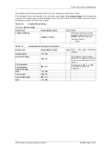
7SG11 Argus Technical Reference
©2013 Siemens Protection Devices Limited
P20007 Page 48 of 71
Type
Fault Record Entry
Description
Group
G
n
Active setting group at time of trip, where
n
is the group number
PHASE A, PHASE B,
PHASE C, EARTH
FAULT, SEF, REF
FWD (or user tag)
Direction
REV (or user tag)
Forward and reverse direction. User-defined text tags can be
programmed for each direction, e.g. LINE, BUS, FEEDER,
TRANSFORMER, etc.
LS
Lowset
DTL
Time-delayed characteristic (set to DTL)
IDMTL
Time-delayed characteristic (set to IDMTL)
HS1
Highset 1
HS2
Highset 2
TIMER 1
SEF/REF 1
st
time delay
TIMER 2
SEF/REF 2
nd
time delay
EXTERNAL TRIP
Trip generated externally and monitored through status input
CB FAIL 1
Circuit breaker fail re-trip
CB FAIL 1 + 2
Circuit breaker fail back-trip
Elements
<
xx>
Element shown e.g. ‘< IDMTL >’ raised the fault trigger
IA=
xxx
Current of phase A is
xxx
IB=
xxx
Current of phase B is
xxx
IC=
xxx
Current of phase C is
xxx
IE=
xxx
Current of earth-fault pole is
xxx
Current
ISE=
xxx
Current of sensitive or restricted earth-fault pole is
xxx
VA=
xxx
Voltage of phase A is
xxx
VB=
xxx
Voltage of phase B is
xxx
VC=
xxx
Voltage of phase C is
xxx
Poles
Voltage
VN=
xxx
Neutral displacement voltage is
xxx
TRIP & RECLOSE
Autoreclose following trip
HOT LINE LOCKOUT
Recloser locked out following trip, due to hot line working active
TRIP & LOCKOUT
Recloser locked out following trip
LINE CHECK TRIP
Trip due to switch onto fault
Auto-reclose
SA TRIP
External trip
General Alarms
(user defined text tag)
A user-defined text tag can be programmed, e.g.’ BUCHHOLZ
TRIP ‘. Multiple Alarms are concatenated with ‘ + ‘ symbols
Example
‘12/05/04 17:25:51.2525 G1 PHASE A LS IDMTL <HS1> HS2 IA = 12.32xIn, PHASE B LS IDMTL HS1 HS2 IB = 12.23xIn, PHASE C LS
IC=0.78xIn, EARTH FAULT LS IDMTL IE=0.27xIn’, BUCHHOLZ TRIP
This specifies the date and time of the trip and that settings group 1 was active at the time of trip. On phase A the
lowset, delayed characteristic, and highsets 1 and 2 were picked up. Phase A highset 1 issued the trip/fault
trigger. Phase A current was 12.32 xIn. On phase B the lowset, delayed characteristic, highset 1 and highset 2
were picked up with a current of 12.23 xIn. On phase C the lowset element was picked up with a current of 0.78
xIn. The earth-fault lowset and delayed characteristic elements were picked up with a current of 0.27 xIn, and a
General alarm ‘
BUCHHOLZ TRIP’
was raised. Basically a Phase A to B fault with some Earth fault component,
Phase C unfaulted.
2.13.3 Waveform (Disturbance) Records
Waveform Record storage is a digital graphical record of analogue current (and for Argus 2 type II voltage) inputs,
status inputs and relay outputs.
Each record is one second in length and is triggered from a protection element operating or from a status input as
designated in the
Data Storage:
Waveform Trig
setting. This allows the user to specify one or more trigger methods:


