7SG11 Argus 4 Diagrams and Parameters
©2013 Siemens Protection Devices Limited
P20010 Page 21 of 22
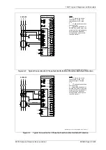
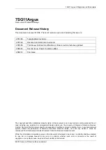
Section 4: Application Diagrams
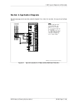
The following pages contain example application diagrams for a variety of connections, showing various hardware
options.
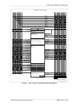
Figure 4-1
Typical Connection for 3 Phase-fault and Earth-fault Protection
P2
P1
S2
S1
P2
P1
S2
S1
P2
P1
S2
S1
Notes
1.
CT circuits are shown
connected to 1A tap - use
alternative tap for 5A rated
CTs.
2.
CT and earth connections
are typical only.
3.
Application shows use of
Holmgreen connection for E/F
circuit. Use of separate ring-
core CT is also possible.
48
47
46
45
52
51
50
49
56
55
54
53
25
26
27
28
13
14
15
3
4
5
6
7
8
9
10
16
17
18
11
12
19
20
S1
RL1
RL2
RL3
RL4
RL5
21
22
RL6
23
24
RL7
43
44
41
42
39
40
37
38
S6
35
36
33
34
31
32
29
30
S2
S3
S4
S5
S7
S8
S9
+
-
+
-
+
-
+
-
+
-
+
-
+
-
+
-
+
-
AG4-401,402
P300004 Argus 4 Connection Diagrams / ArG1-401,402
A
B
C
BUSBARS
Rx
Tx
Rear F.O.
comms ports
see note 3
A
B
C
E/F
1A
5A
1A
5A
1A
5A
1A
5A


