7SG11 Argus Technical Reference
©2013 Siemens Protection Devices Limited
P20007 Page 31 of 71
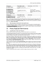
Setting name
Range (
bold
= default)
Units Notes – see note 1 below
Gn SEF/REF Starter
_, 1 for each output contact
(default:
_ _ _ _ _ _ _ _ _ _ _
)
Gn SEF/REF Delay 1
Gn SEF/REF Delay 2
Gn SEF/REF Lowset
GnF SEF/REF Block
GnR SEF/REF Block
_, 1 for each output contact
(default:
_ 1 _ _ _ _ _ _ _ _ _
)
see note 1 below
default settings – all Protection
elements energise the Trip output
relay 2.
Sub-menu:
Status Config.
Setting name
Range (
bold
= default)
Units Notes
Gn SEF/REF Delay 1 Inhib.
Gn SEF/REF Delay 2 Inhib.
Gn SEF/REF Lowset Inhib.
_, 1 for each status input
(default:
_ _ _ _ _ _ _ _ _
)
Note 1. On the single-pole directional SEF model, if the directional control is set to tri-state these settings will be
duplicated for forward and reverse directions. The settings for the forward direction are indicated by an ‘F’
following the group number (e.g.
GnF SEF Current Setting
), while the settings for the reverse direction are indicated
by an ‘R’ (e.g.
GnR SEF Current Setting
).
2.4.1 High Impedance Restricted Earth-fault Scheme
Externally mounted power resistors, connected in series with the relay, are required to set the stability voltage V
S
.
See Section 3: Application Notes for the theory and formulae required to calculated the I
S
and V
S
settings and
resistor values. A non-linear resistor may also be required to protect the scheme wiring and current transformers
against transient over-voltages at high fault levels.
2.5 Primary Equipment Fail Protection
2.5.1 Circuit Breaker (Trip) Fail Protection
Provides 50CBF Trip Fail two-stage time delay with Phase, Earth and SEF current level detectors.
If the Circuit Breaker (CB) fails to respond to a Trip output and fault current continues to flow, then the ARGUS
Circuit Breaker Fail (CBF) function can be set to automatically issue a graded, time-delayed, CBF 1 output (Re-
trip) then, if that fails, a second CBF 2 output (Back Trip to an up-stream CB).
Any Protection element or Status input for which a Trip output is required must be mapped to an output relay
which in turn is mapped to ‘Fault Trigger’. When ‘Fault Trigger' is raised this enables the CBF current level
detectors that check for cessation of current flow in each pole. If and while any current exceeds setting, specified
by
Protection:P/F
CB Fail Setting, Protection:E/F CB Fail Setting or Protection:SEF CB Fail Setting,
then CBF Time delay 1
timer, specified by
Protection:
CB Fail Time Delay 1
, runs. On time-out the CB Fail 1 output is raised, this can be
mapped to another output relay to provide a re-trip output.
A second CBF timer, specified by
Protection:
CB Fail Time Delay 2
, then starts and runs if and while current exceeds
setting. On time-out CB Fail 2 output is raised, this can be mapped to a different output relay to provide a Back-
trip output.
NB:- If CBF is to be applied then a current setting should be entered for all poles i.e. P/F & E/F & SEF settings.
Typical settings will be below the protection settings applicable for each pole; phase fault setting can normally be
above maximum Load current. The CBF scheme will then run until all currents fall below the set detector levels. If
any CBF current setting is set to OFF i.e. Zero current, then, once enabled, the CBF function will run until all
currents are zero. Grading time margins and settings will be typically 200ms for CB Fail Time delay 1, and 200ms
for CB Fail Time delay 2.
If CBF is not required then CBF Time delay 1 and CBF Time delay 2 should be set to OFF i.e. Infinity.


