


Operating Instructions
Chapter
7
UE 440/470
8 010 432/P097/14-03-05
© SICK AG • Industrial Safety Systems • Germany • All rights reserved
59
Application and switching
examples
Application A
Application B
Single channel inputs
$
Reset
$
EDM
$
Reset
$
EDM
$
Safety switch tested
$
Safety switch tested
Dual channel inputs
$
Emergency stop input device tested (switches both
applications)
EFI inputs
$
C 4000 receiver
$
C 4000 receiver
$
"Reset required" signal lamp
$
"Reset required" signal lamp
Single channel
outputs
$
Two test outputs for testing of single or dual channel inputs
(tests are offset by time for detection of cross circuits)
Dual channel outputs
$
OSSD A
$
OSSD B
Marginal conditions
$
Both OSSDs are monitored for cross circuits.
$
The connection cables of the dual channel safety switches are
installed in separate sheathing lines or protected.
$
EDM and contactors are wired within the control cabinet.
$
The connection cables of both reset buttons are installed in
separate sheathing lines or protected.
Result
The UE 440 reaches a value of
14
)
% PFD at SIL 3 in
application A with the specified
marginal conditions after
10 years.
The UE 440 reaches a value of
15
)
% PFD at SIL 3 in
application B with the specified
marginal conditions after
10 years.
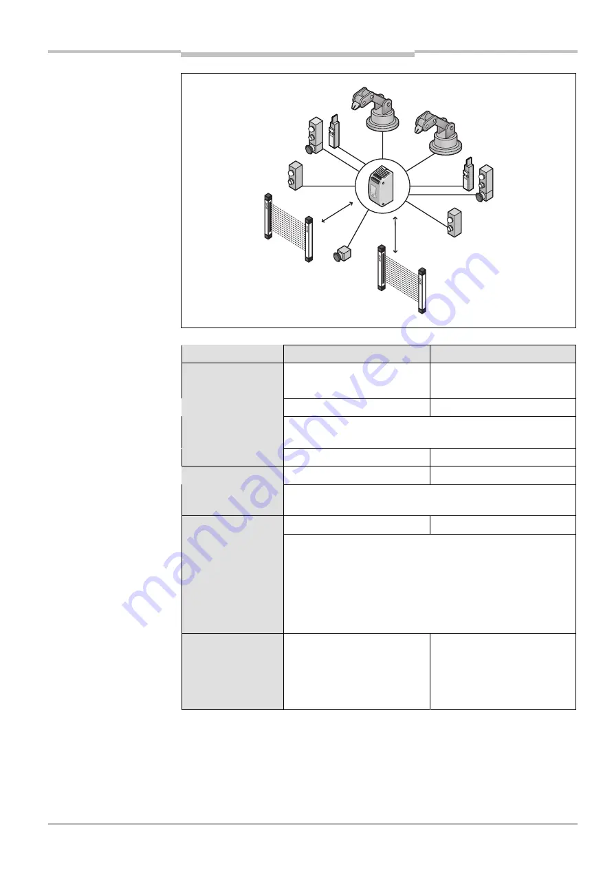
FIg. 34: Components of the
access protection for two
robot cells
Tab. 17: Failure probability
according to IEC 61 508 for
the example access
protection for two robot cells