&
S a f e t y C o n t r o l l e r
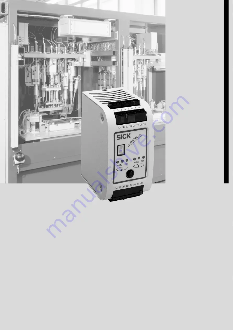
U E 4 4 0 / U E 4 7 0
O
PERATING
I
NSTRUCTIONS
Page 1: ... S a f e t y C o n t r o l l e r U E 4 4 0 U E 4 7 0 O P E R A T I N G I N S T R U C T I O N S ...
Page 2: ...5 This document is protected by copyright The SICK AG company retains this right Reproducing this document in whole or part is only permissible within the limits of the statutory regulations of copyright law Modifying or abridging this document is impermissible without express written permission from the SICK AG company ...
Page 3: ...ctions 17 4 1 Base settings with the configuration wizard 17 4 1 1 Configuration name 17 4 1 2 Operating modes and operating mode selector switch 18 4 1 3 Automatic reconfiguration 20 4 2 Protective operation 20 4 2 1 Electro sensitive protective equipment 22 4 2 2 OSSDs of the UE 440 470 23 4 2 3 Signal output ADO 23 4 2 4 Devices and sensors 24 4 2 5 Two hand control 25 4 2 6 Emergency stop 25 4...
Page 4: ...d sensors 49 6 2 3 Two hand control 50 6 2 4 Single channel emergency stop 50 6 2 5 Dual channel emergency stop 51 6 2 6 Key operated switch for bypass 51 6 2 7 Reset button 51 6 2 8 Machine cycle contacts 52 6 2 9 Teach in key operated switch for C 4000 53 6 2 10 Operating mode selector switch 53 6 2 11 External device monitoring EDM 54 6 3 Connection of active sensors 55 6 3 1 Electro sensitive ...
Page 5: ...78 9 2 Offline configuration 78 9 3 Online configuration 78 9 4 Configuration memory 79 10 Fault diagnosis 80 10 1 In the event of faults or errors 80 10 2 SICK support 80 10 3 LED displays 81 10 4 Displays of the 7 segment display 81 10 5 Extended diagnostics 85 11 Technical data 86 11 1 Response times of OSSDs A and B 86 11 1 1 Examples 88 11 2 Data sheet 90 11 3 Dimensional drawing 94 12 Orderi...
Page 6: ...re addressed to planning engineers machine designers and the operators of systems which are to be protected by one or more SICK protective devices in connection with a safety controller UE 440 470 It also addresses people who integrate a UE 440 470 into a machine initialise its use or who are in charge of servicing and maintaining the unit 1 3 Scope These operating instructions apply for the safet...
Page 7: ...470 These operating instructions in different languages for viewing and printing 1 5 Abbreviations Application diagnostic output configurable signal output that indicates a specific status Bottom dead centre machine cycle contact Indicates that the bottom dead centre has been reached on a press Electro sensitive protective equipment e g C 4000 or S 3000 C 4000 safety light curtain SICK Configurati...
Page 8: ... is illuminated constantly The LED is flashing The LED is off Instructions for taking action are shown by an arrow Read carefully and follow the instructions for action Warning A warning indicates concrete or potential dangers They save you from harm Read warnings carefully and abide by them Software notes show the location in the CDS Configuration Diagnostic Software where you can make the approp...
Page 9: ... connected to the safety controller and have read and familiarised themselves with them 2 2 Applications of the device The safety controller UE 440 470 is a configurable controller for comprehensive implementation of safety applications The device corresponds to category 4 according to EN 954 1 applications can reach SIL3 according to IEC 61508 The emergency stop function in the device corresponds...
Page 10: ... in particular Machinery Directive 98 37 EC Provision and use of Directive 89 655 EEC Low Voltage Directive 73 23 EEC Work safety regulations safety rules Other relevant health and safety regulations Manufacturers and owners of the machine on which a UE 440 470 is used are responsible for obtaining and observing all applicable safety regulations and rules The notes in particular the test notes see...
Page 11: ... this device Contact your local SICK representative 2 5 2 Material separation Material separation may only be performed by specialist personnel Exercise care when disassembling the devices The danger of injury is present Before you can turn over the devices for environmentally friendly recycling you must separate the different materials of the UE 440 470 from one another Separate the housing from ...
Page 12: ...tc of an operating mode selector switch for switching between up to five operating modes 8 outputs which can be used as single channel control or signal outputs for downstream controllers e g EPLC or others as dual channel OSSDs for the connection of e g actuators or EPLC for the connection of signal lamps as outputs for test signals for single or dual channel sensors or input devices such as emer...
Page 13: ...hin a safety application the safety controller processes specific signals of optical and tactile sensors The safety controller also expands the functions of connected systems such as C 4000 or S 3000 PSDI mode simultaneous protective field monitoring Using the Configuration Diagnostics Software CDS you can link the connected components to one another Predefined software function modules used to im...
Page 14: ...put device Single or dual channel input devices Two hand input device dual channel Key operated switch for bypass Reset button External device monitoring Switch for switching monitoring fields at S 3000 and for blanking field switching at C 4000 Teach in key operated switch for teaching in blanked areas with C 4000 Machine cycle contacts TDC BDC SCC with UE 470 Sensors must be active HIGH Fig 2 Li...
Page 15: ... on the front of the safety controller The LEDs are grouped into two blocks The left block indicates the conditions of outputs 02 0 and 02 1 and the right block deals with outputs 02 2 and 02 3 If the dual channel outputs are used as OSSDs they have the following meaning Display Meaning red OSSD 02 0 AND 02 1 switched off green OSSD 02 0 AND 02 1 switched on yellow Reset of the application configu...
Page 16: ...eaning green 02 0 AND 02 1 HIGH red With all other conditions of outputs 02 0 and 02 1 yellow Reset of the application configured above in the CDS required Display Meaning green 02 2 AND 02 3 HIGH red With all other conditions of outputs 02 2 and 02 3 yellow Reset of the application configured below in the CDS required Display Meaning System ready for operation System initialisation Configuration ...
Page 17: ...es integrated into the safety application Note the warnings and function descriptions of protective devices connected to the safety controller Contact the respective manufacturer of the protective device if in doubt Functions such as the restart interlock PSDI etc can be configured in both the UE 440 470 and in a device connected via EFI The UE 440 470 does not check whether or not these functions...
Page 18: ...onfigured individually for each operating mode A configured input element should generally be used in all operating modes and connected to other elements for this reason The CDS checks whether this is the case when saving the application If the CDS determines that an input element is not used in all operating modes you are notified of this and must confirm this explicitly If you do not wish to use...
Page 19: ... laser scanner S 3000 then there is a switching between the monitoring cases The OSSD of the S 3000 can remain switched on during this switch depending on the protective field status The OSSDs of the safety controller are switched off however Only C4000 Receivers with the following type label entry are to be used Software Version 3 28 or higher Operating mode selector switch The operator can switc...
Page 20: ... the functions described below you must position a function module for protective operation in the CDS Two function modules are available for protective operation Standard function module Standard function module with machine cycle contact evaluation UE 470 The function module for protective operation can have the following inputs Input Effect ESPE Switch If an ESPE connected to this input or a sw...
Page 21: ...set button or external device monitoring when the application is started or after the OSSDs are switched off The output of the release module signals a logical 1 releases when the necessary input criteria are met AND link at all the inputs used Input Input criterion Reset A reset button connected to the release module was actuated signal sequence 0 1 0 present Reset2 An input device connected to t...
Page 22: ... from the protective device or transferred to it depends on the respective protective device e g S 3000 or C 4000 When transferring the status of an operating mode selector switch to a device connected via EFI the same number of operating modes must be configured there The connection of the C4000 Sender via EFI is not allowed When determining the safety distance of the protective devices take the ...
Page 23: ...3 Signal output ADO You can configure up to eight configurable signal outputs ADO for the UE 440 470 With the aid of the respective signal output the safety controller can signal specific states You can use this output for a relay or a PLC for example You can configure the signal outputs as inverted signal outputs too If an output is configured as an inverted signal output it is in standby mode HI...
Page 24: ...tion draft in Edit configuration draft window context menu element symbol single channel input device or sensor command Element wizard The electrical connection of the single channel input devices and sensors is described in Chapter 6 Electrical installation on Page 49 Dual channel input devices and sensors You can configure up to seven connections for dual channel input devices and sensors For a ...
Page 25: ... You can configure connections for two hand control The output of the two handed input element can e g be wired to the release module the protective module or the logic module of partial application A or B The electrical connection of the two hand control is described in Chapter 6 Electrical installation on Page 50 4 2 6 Emergency stop Stop category 0 or 1 according to EN 418 can be implemented vi...
Page 26: ...f the emergency stop input device Single channel emergency stop For a single channel emergency stop input device you configure whether testing is to occur constantly see Page 42 whether an input delay is necessary see Page 42 You must use an N C contact as the single channel emergency stop input device Context menu device symbol UE 440 470 command Edit configuration draft in Edit configuration dra...
Page 27: ...safe operational status e g after contactor failure the system locks and shuts down completely see The Lock out operating status on Page 80 The 7 segment display will then show the error message There is no contactor monitoring EDM during Bypass Connection of the external device monitoring You can configure up to two connections for external device monitoring Note the assignment of both connection...
Page 28: ... are released after the connected reset button is actuated if the remaining initial conditions are also in effect see Section 4 2 12 Release of the application with a release module on Page 33 With the machine control s external restart interlock A reset button connected to the UE 440 470 does not influence the machine restart The possible combinations are shown in the following table Restart inte...
Page 29: ...tuating the reset button for the internal restart interlock providing the initial conditions are in effect the UE 440 470 switches the OSSD s on the neighbouring LED of the respective OSSD illuminates green The external restart interlock prevents the machine from restarting The operator must also actuate the restart button of the machine control after resetting the UE 440 470 Ensure that the prope...
Page 30: ...levels or by two input signals that are independent of each other e g two position switches If you implement PSDI mode with a UE 470 you may not configure a bypass It must be possible to view the entire hazardous point when pressing the key operated switch for bypass It may not be possible to actuate the key operated switch for bypass in the hazardous area The bypass function is not in effect unti...
Page 31: ...rly Using organisational measures ensure that the key operated switch for bypass is actuated once after a certain interval This is necessary so that the UE 440 470 can identify an error condition of the key operated switch for bypass or an error condition in its connection cable which occurs up until then The interval is to be defined to suit the specific case dependant on the application Constant...
Page 32: ...witches off after the shutdown delay has passed for example through someone entering the Protective Field or the switching of the operating mode and the machine or system stops Shutdown of the machine or system can no longer be prevented If you have not configured an internal restart interlock at the UE 440 470 output Out2 does not switch off and the machine or system continues running An entry in...
Page 33: ...he device Use this opportunity to for example be able to clearly distinguish between two configured applications Use the name of the monitored machine or system for example Context menu device symbol UE 440 470 command Edit configuration draft in Edit configuration draft window context menu element symbol function module command Element wizard Application tab 4 3 PSDI mode with safety controller U...
Page 34: ... at the top dead centre and then waits for a valid PSDI interruption in the ESPE If the operator now interruptions in the protective field and then retreats the safety controller releases movement If another interruption occurs during the dangerous movement however the safety controller immediately cuts off the dangerous movement 2 PSDI mode In comparison to 1 PSDI mode 2 PSDI mode means that the ...
Page 35: ...ycle contacts for PSDI mode operation To form the PSDI mode safely and in accordance with the application the UE 470 evaluates three machine signals Overrun monitoring SCC The evaluation of overrun monitoring is optional Bottom dead centre BDC Top dead centre TDC Within the pin assignment for the UE 470 you can configure one connection each for the SCC BDC and TDC machine cycle contacts On the bas...
Page 36: ...ange at the same time or with the same polarity they are monitored for simultaneous same polarity changes If a simultaneous and same polarity signal change occurs with several machine cycle contacts the OSSDs of the safety controller are switched off the error message O appears in the 7 segment display The UE 470 does not offer control and monitoring functions for reverse operations or single stro...
Page 37: ...illuminated constantly Reach once or twice into the protective field according to the PSDI mode Press the reset button Press the reset button Reach once or twice into the protective field according to the PSDI mode Reach once or twice into the protective field according to the PSDI mode Start sequence Procedure The machine runs until it reaches the top dead centre and waits there for the PSDI A la...
Page 38: ...rrun monitoring the UE 470 monitors whether the SCC is still closed before the stroke release i e whether the machine has actually stopped at the top dead centre If the press exceeds the SCC before the operator has interrupted once or twice depending on the PSDI mode the UE 470 switches to the operating mode Lock out see Page 80 The SCC contact must be connected for overrun monitoring 4 3 7 Deacti...
Page 39: ... the BDC 4 3 9 PSDI signal lamp You can configure a PSDI signal lamp within the pin assignment for the UE 470 The connected signal lamp illuminates if a PSDI interruption in protective field is expected The electrical connection of the PSDI signal lamp is described in Chapter 6 Electrical installation on Page 56 4 4 Evaluation of device specific EFI status bits The device specific EFI status bits ...
Page 40: ... is initiated at the C 4000 the OSSD of the C 4000 switches off during the teach in The behaviour of the OSSDs of the UE 440 470 depends on how the OSSD of the C 4000 or the status information of its OSSD are integrated in the application via EFI Bypass is not possible during teach in If the operating mode at the UE 440 470 is changed during the teach in the teach in procedure is completed first O...
Page 41: ...ation draft window context menu element symbol teach in key operated switch for C 4000 command Element wizard The electrical connection of the teach in key operated switch is described in Chapter 6 Electrical installation on Page 45 4 6 Settings for overlapping functions 4 6 1 Complementary or equivalent input evaluation Complementary evaluation For proper switching one channel must always be wire...
Page 42: ...als for example or cross circuit detecting or preventative measures Context menu device symbol UE 440 470 command Edit configuration draft in Edit configuration draft window context menu element symbol of the sensor command Element wizard Testing tab 4 6 3 Input delay To mute bounce times of a input device or sensor you can enter an input delay For the settable input delay refer to the Data sheet ...
Page 43: ...iscrepancy time has expired both inputs of the connection are not in equivalent the same states with equivalent circuit are not in complementary opposite states with complementary circuit In this case the OSSDs of the safety controller are switched off and the error message T O appears in the 7 segment display For the settable discrepancy time refer to the Data sheet on Page 90 Context menu device...
Page 44: ...tion The safety controller UE 440 470 is designed for installation on a 35 mm mounting rail in accordance with EN 50 022 The positioning place must at least comply with enclosure rating IP 54 The following steps are necessary after mounting and installation Completing the electrical connections Chapter 6 Commissioning Chapter 8 Configuration Chapter 8 3 1 ...
Page 45: ...atibility EMC functional earthing FE must be connected The control cabinet or assembly casing of the UE 440 470 must at least comply with enclosure rating IP 54 You must connect the UE 440 470 to the same voltage supply as the connected protective devices The voltage supply of the devices must be capable of buffering brief mains voltage failures of 20 ms as specified in EN 60 204 1 The cables of a...
Page 46: ...inal strips with eight pins each The individual terminal strips are encoded to prevent mix ups Use only encoded connections and label them Dangerous faults could arise if the terminal strips are swapped and this goes undetected Fig 12 Connections of the UE 440 470 ATTENTION 1 2 3 4 5 6 7 8 Encoding Terminal strip II 17 18 19 20 21 22 23 24 25 26 27 28 29 30 31 32 9 10 11 12 13 14 15 16 Terminal st...
Page 47: ...hannel or can be used as switching output dual channel switch off of a machine or system 29 O2 2 15 O2 3 Signal output single channel or can be used as switching output dual channel switch off of a machine or system 31 EFI1B 10 EFI1A Device communication for ESPE with EFI 11 FE Functional earthing for applying shielding of EFI1 if shielding is necessary for EMC reasons 9 EFI2A 22 EFI2B Device comm...
Page 48: ... The configuration connection is found on the front of the safety controller Ensure protection from static electricity discharge before connecting the configuration cable see Section 12 3 2 CDS and connection cable on Page 95 Always remove the plug from the configuration connection once you have completed configuration Fig 13 Configuration connection M8 4 Notes Configuration connection ...
Page 49: ...ice or sensor If you have configured input devices or sensors without testing connect them to 24 V DC If you have configured input devices or sensors with testing connect them to the test outputs of the safety controller 6 2 2 Dual channel input devices and sensors You can connect several dual channel input devices and sensors to the UE 440 470 Prevent cross circuits with non testable dual channel...
Page 50: ...oller You can use N C contacts or N O contacts with equivalent input devices With complementary evaluation you decide the connection to which the N C contact or N O contact is attached during configuration 6 2 3 Two hand control 24 V I 1 0 I 1 1 I 1 2 I 1 3 You can connect two two hand control input devices to the UE 440 470 6 2 4 Single channel emergency stop You can connect one emergency stop fo...
Page 51: ...pendent of each other e g two position switches You can use a complementary or equivalent switching key operated switch Mount the key operated switch for bypass in such a way that the hazardous point is completely visible when the key operated switch is used With equivalent evaluation the contacts of the key operated switch for bypass must be dual channel N O contacts With complementary evaluation...
Page 52: ...nal You must ensure that the machine cycle contacts meet the following criteria Machine cycle contact Criteria TDC The contact is normally closed The contact must be open for at least 100 ms before reaching the top dead centre The contact must be closed again at the top dead centre BDC Contact is implemented with one or two 1 channel NO contacts At the end of the dangerous movement the contact mus...
Page 53: ...e safety controller Using the operating mode selector switch you can switch between the operating modes of the safety controller and also switch the operating modes of the connected protective device e g the hidden areas with a safety light curtain C 4000 The operating mode selector switch must be a key operated switch Use an operating mode selector switch that has only the same number of switch s...
Page 54: ...h N C contacts k1 k2 when the contact elements K1 K2 reach their de energised position after the protective device has responded 24 V is then applied at the input of the EDM If all criteria for switching on the OSSD are fulfilled and the 24 V are not connected one of the contact elements is defective and the external device monitoring prevents switch on of the OSSD Spark suppressed contactors exte...
Page 55: ...onnect the ESPE to the dual channel inputs of the safety controller and via EFI corresponds to SDL see Fig 27 The OSSD status is passed on to the safety controller via the OSSD inputs and the other status information is passed on to it depending on the configuration in the CDS via EFI If the OSSD status is passed on to the UE 440 470 via EFI the response time of the OSSDs of the safety controller ...
Page 56: ...n only connect a PSDI signal lamp to the safety controller UE 470 6 4 4 Signal output ADO You can make various signals of the UE 440 470 available at the outputs e g for a relay or an EPLC Fig 28 Example for connection of a Reset required signal lamp Fig 29 Example for connection of a Bypass signal lamp Note Fig 30 Example for connection of a PSDI signal lamp Fig 31 Example for connection of signa...
Page 57: ... Safety Systems Germany All rights reserved 57 Electrical installation 6 4 5 Test outputs The outputs 01 0 and 01 1 are used as test outputs The example shows the connection of a single channel and two dual channel sensors Fig 32 Example for the connection of several sensors with testing ...
Page 58: ...via EFI Two safety applications application A and B were configured in the UE 440 The OSSD of the respective safety application is switched off due to the interruption of a protective field The side access doors to the robot cells are monitored by safety switches If the doors are opened the safety switches also switch off the OSSD of the respective safety application A restart interlock is configu...
Page 59: ...ross circuits Dual channel outputs OSSD A OSSD B Marginal conditions Both OSSDs are monitored for cross circuits The connection cables of the dual channel safety switches are installed in separate sheathing lines or protected EDM and contactors are wired within the control cabinet The connection cables of both reset buttons are installed in separate sheathing lines or protected Result The UE 440 r...
Page 60: ...hed off due to the interruption of a protective field The side access door to the robot cell is monitored by a safety switch If the door is opened the safety switch also switches off the OSSD of the safety application An internal restart interlock is configured for the safety application A signal lamp indicates that a reset is required after switch off of the OSSD The OSSD of the UE 440 is reactiv...
Page 61: ...quired signal lamp Single channel outputs Two test outputs for testing of single or dual channel inputs tests are offset by time for detection of cross circuits Dual channel outputs OSSD A Marginal conditions The OSSD is monitored for cross circuits The connection cables of the dual channel safety switches are installed in separate sheathing lines or protected EDM and contactors are wired within t...
Page 62: ...as of two robot cells are protected via a UE 440 with a safety laser scanner S 3000 Two safety applications are configured in the UE 440 for this The S 3000 monitors both hazardous areas with two simultaneous protective fields The OSSD of the respective safety application is switched off due to an object in one of the protective fields Fig 38 Connection of the access protection with point of opera...
Page 63: ... safety application A restart interlock is configured for both safety applications Two independent signal lamps and indicate that a reset is required after one of the OSSDs is switched off The respective OSSD of the UE 440 is reactivated by actuating the connected reset button and Three emergency stop input devices are connected and switch off both safety applications robot cells simultaneously Ea...
Page 64: ... Dual channel outputs OSSD A OSSD B Marginal conditions Both OSSDs are monitored for cross circuits The connection cables of the dual channel safety switches are installed in separate sheathing lines or protected EDM and contactors are wired within the control cabinet The connection cables of both reset buttons are installed in separate sheathing lines or protected Result The UE 440 reaches a valu...
Page 65: ...ch you can switch between the various operating modes e g 1 PSDI mode 2 PSDI mode Set up An enabling switch is active in the Set up operating mode and switches the OSSD off as soon as the operator leaves the enabling position of the switch A restart interlock is configured for the safety application A signal lamp indicates that a reset is required after switch off of the OSSD The OSSD of the UE 47...
Page 66: ...rear of the press and switch both applications off Application A Application B Reset EDM TDC BDC SCC Reset EDM Single channel inputs Operating mode selector switch for both applications Enabling switch tested Dual channel inputs Emergency stop input device tested switches both applications EFI inputs C 4000 C 2000 Reset required signal lamp Reset required signal lamp Single channel outputs Two tes...
Page 67: ...eathing lines or protected Result The UE 470 reaches a value of 21 PFD at SIL 3 in application A with the specified marginal conditions after 10 years The UE 470 reaches a value of 21 PFD at SIL 3 in application B with the specified marginal conditions after 10 years In accordance with Standard EN 963 the machine cycle contact BDC must be implemented with two independent signals e g two 1 channel ...
Page 68: ...he safety switch also switches off the OSSD A restart interlock is configured for the safety applications A signal lamp indicates that a reset is required after switch off of the OSSD The OSSD of the UE 440 is reactivated by actuating the connected reset button The interior area of the press is monitored via an S 3000 once the OSSD has switched off If a person is found in the interior area of the ...
Page 69: ...oss circuits Dual channel outputs OSSD A Marginal conditions The OSSD is monitored for cross circuits The connection cables of the dual channel safety switches are installed in separate sheathing lines or protected EDM and contactors are wired within the control cabinet The connection cables of the reset button are installed in separate sheathing lines or protected Result The UE 440 reaches a valu...
Page 70: ... of the respective safety application is switched off due to the interruption of a protective field The side access door to the front robot cell is monitored by a safety switch If the door is opened the safety switch also switches off the OSSD of the front safety application in the example A restart interlock is configured for both safety applications Two independent signal lamps and indicate that...
Page 71: ...cross circuits Dual channel outputs OSSD A OSSD B Marginal conditions Both OSSDs are monitored for cross circuits The connection cables of the dual channel safety switches are installed in separate sheathing lines or protected EDM and contactors are wired within the control cabinet The connection cables of both reset buttons are installed in separate sheathing lines or protected Result The UE 440 ...
Page 72: ...ructions UE 440 470 72 SICK AG Industrial Safety Systems Germany All rights reserved 8 010 432 P097 14 03 05 Application and switching examples Fig 50 Connection of the hazardous point protection with hazardous area protection ...
Page 73: ...t against being entered by people e g set up warning signs attach blocking ropes or similar Observe the relevant laws and local regulations 8 1 Sequence for commissioning When commissioning the entire system you must prevent faults in the sub systems by following a specialised sequence for commissioning First commission the devices at the EFI connections and test their system behaviour Please read...
Page 74: ...ration Check whether the loaded configuration fits one of the C 4000 Standard Advanced connected via EFI Fig 51 System self check after switching on Loading of saved configuration 7 segment display shows Internal self test Automatic reconfiguration activated Type code correct Serial number correct Configuration date and time correct 7 segment display shows Waiting for configuration Yes Yes Yes Rec...
Page 75: ...ion memory on Page 79 or 2 or 3 System ready for operation Other display Safety lock activated Malfunction in device or in connected actuators or sensors or their wiring See Chapter 10 4 Displays of the 7 segment display on Page 81 Display Red Green Yellow Meaning OSSD deactivated Reset required OSSD activated OSSD deactivated Other display Malfunction in device or in connected actuators or sensor...
Page 76: ...missioning The purpose of the initial commissioning tests is to confirm the safety requirements specified in the national international rules and regulations especially in the Machine and Work Equipment Directive EC Conformity Check the effectiveness of the protective device mounted to the machine using all selectable operating modes as specified in the checklist in the Annex see Checklist for the...
Page 77: ...teps Offline configuration of the UE 440 470 to determine the electrical connections of the safety controller Context menu device symbol UE 440 470 command Configuration draft Edit Possible offline configuration of the connected ESPE from SICK AG Context menu device symbol connected EFI device e g C 4000 command Configuration draft Edit Electrical installation of the UE 440 470 and the ESPE sensor...
Page 78: ...ment for the safety controller in the CDS and configure your safety application s for this purpose read Chapter 4 Configurable functions from Page 17 Please also read the user manual for the CDS and use the online help of the program If desired configure the connected ESPE from SICK AG in the CDS as well Please read the corresponding operating instructions of the ESPE and the user manual for the C...
Page 79: ...ging ESPE with the same type code the configuration is transferred to the ESPE automatically Fully decommission the system Exchange the ESPE as described in the operating instructions Recommission the system see Chapter 8 Commissioning on Page 73 The 7 segment display runs through the switch on sequence and then shows Any configuration saved in the safety controller of one or more pieces of ESPE i...
Page 80: ...ee Chapter 8 3 Test notes on Page 76 The Lock out operating status With certain malfunctions or a faulty configuration the UE 440 470 enters the safe Lock out status The 7 segment display of the safety controller shows the corresponding error To place the device back in operation Rectify the cause of the malfunction as per Tab 26 Switch the voltage supply of the UE 440 470 off and back on again 10...
Page 81: ...tective field of the connected ESPE is unoccupied OSSD switched off Reset required Press the reset button 10 4 Displays of the 7 segment display This section explains the meaning of the 7 segment display A description of the positions and symbols used at the UE 440 470 is found in Section 3 3 Display elements on Page 15 Display Possible cause How to remedy the error System ready for operation No e...
Page 82: ...ired incorrectly and remedy the fault if necessary For Switch the device off and back on again 0 Error of the reset button or two handed input device Check the reset button two handed input device for correct function The button input device may be defective or stuck Check the wiring of the reset button two handed input device for any short circuit to 24 V 3 The key operated switch for bypass was ...
Page 83: ...ion Ensure that both contacts on the key operated switch for bypass are switched within the configured discrepancy time T O 0 Short circuit after 24 V at operating mode selector switch Check the wiring of the operating mode selector switch Check the operating mode selector switch 6 UE 440 470 defective Send the safety controller to the manufacturer for repair 7 Overcurrent at a 1 channel output or...
Page 84: ... 0 V Check the wiring for short circuit to 0 V _ O Overvoltage at OSSD B connection 2 Check the connected switching element Replace if necessary Check the wiring for short circuit to 0 V _ O Short circuit at OSSD B connection 2 after 24 V Check the wiring for short circuit to 24 V _ O Short circuit at OSSD B connection 2 after 0 V Check the wiring for short circuit to 0 V _ O Short circuit at OSSD...
Page 85: ...e machine cycle contacts Ensure that these are correctly connected and configured Replace if necessary Z Emergency stop was actuated No error The UE 440 470 waits until the emergency stop signal is retrieved again All outputs are inactive Switch the voltage supply of the UE 440 470 off and back on again If you experience difficulties while remedying errors faults contact SICK support Also have a p...
Page 86: ... safety controller the response times of the devices connected to the safety controller a configured input delay for the inputs of the UE 440 470 if the connected input devices and sensors affect the OSSDs Example A safety switch secures the entry to a robot cell and opening of the door switches one of the OSSDs off A configured input delay increases the response time of the OSSD the transfer time...
Page 87: ...10 ms 4 Set shutdown delay ______ ms 5 Response time of the OSSDs _______ ms How to determine the response time of an OSSD for the response of a protective device connected via EFI Determine the response time of the connected input device or sensor using the respective operating instructions Fill out the following table to determine the response time of this signal path Line Required detail Time 1...
Page 88: ...ms 4 Internal processing time of the safety controller 10 ms 5 Set shutdown delay 0 ms 6 Response time of the OSSDs 94 ms Transfer of the OSSD status via EFI You accept the OSSD status of an S 3000 via EFI Line Required detail Time 1 Response time of ESPE 120 ms 2 Additional value for the transfer time of OSSD status information via EFI S 3000 21 ms 21 ms 3 Internal processing time of the safety c...
Page 89: ...g mode 2 you have not configured a shutdown delay Line Required detail Time 1 Response time of ESPE 64 ms 2 Set input delay 10 ms 3 Internal processing time of the safety controller 10 ms 4 Set shutdown delay 30 ms 5 Response time of the OSSDs 114 ms Line Required detail Time 1 Response time of ESPE 64 ms 2 Set input delay 10 ms 3 Internal processing time of the safety controller 10 ms 4 Set shutd...
Page 90: ...urrent consumption 4 5 A Operating temperature 0 C 50 C Storage temperature 25 C 80 C Air humidity non condensing 35 85 Power up delay after connecting the voltage supply 3 s Function data Active PSDI time limit for hydraulic presses configurable 5 s 500 s Muting for eccentric presses 30 s EFI connections secure SICK device communication Cable length for 500 kbps and 0 5 mm cables 50 m Cable type ...
Page 91: ...tected6 cross circuit monitored Response time See Section 11 1 Response times of OSSDs A and B on Page 86 Shutdown delay configurable 0 ms 300 s Switch off time 5 ms Switch on time once the necessary signals are present at the inputs 10 ms Switching voltage7 HIGH active Ueff Uv 2 7 V Uv Switching voltage7 LOW inactive 0 V 0 V 3 5 V Switching voltage 0 mA 500 mA Leakage current8 0 25 mA Load capaci...
Page 92: ... V 3 V Signal output O1 3 Output voltage HIGH UV 3 5 V UV Output current HIGH 275 mA Current limit 300 mA 500 mA Internal resistance to 0 V switched off 3 7 k Minimum current undervoltage detection 20 mA Output voltage LOW 0 V 0 V 3 V Configuration and diagnostics interface Communication protocol RS 232 proprietary Transfer speed 9600 baud 19200 baud 38400 baud 57600 baud Cable length for 9000 kbp...
Page 93: ...ion capacity 2 conductors of the same diameter Diameter of fixed wires 0 2 mm 1 mm Diameter of flexible wires 0 2 mm 1 5 mm Diameter of flexible wires with wire end ferrules no plastic sheath 0 25 mm 1 mm Diameter of flexible wires with TWIN wire end ferrules with plastic sheath 0 5 mm 1 5 mm Permissible cable resistance between supply cables 1 Permissible cable resistance between cables and load1...
Page 94: ...ons UE 440 470 94 SICK AG Industrial Safety Systems Germany All rights reserved 8 010 432 P097 14 03 05 Technical data 11 3 Dimensional drawing Fig 53 Dimensional drawing of UE 440 470 mm 65 109 4 79 2 3 6 3 7 106 8 119 6 74 4 148 9 ...
Page 95: ...coded screw connection terminal strips including blank fields in bag 2 029 991 12 3 2 CDS and connection cable Part Description Part number CDS Configuration Diagnostic Software on CD including online documentation and operating instructions in all available languages 2 026 875 Release code of CDS software Release code of CDS software Enables configuration and online diagnostics of the UE 440 470 ...
Page 96: ...Chapter 13 Operating Instructions UE 440 470 96 SICK AG Industrial Safety Systems Germany All rights reserved 8 010 432 P097 14 03 05 Annex 13 Annex 13 1 Declaration of conformity ...
Page 97: ... rules and regulations been observed in compliance with the directives standards applicable to the machine Yes No 2 Are the applied directives and standards listed in the declaration of conformity Yes No 3 Does the protective device comply with the required category Yes No 4 Are the required protective measures against electric shock in effect protection class Yes No 5 Has the protective function ...
Page 98: ...C 61 508 for the example access protection with point of operation protection 61 Tab 19 Failure probability according to IEC 61 508 for the example simultaneous hazardous area protection 64 Tab 20 Failure probability according to IEC 61 508 for the example hazardous point protection with PSDI mode 66 Tab 21 Failure probability according to IEC 61 508 for the example hazardous point protection with...
Page 99: ...devices or sensors 50 Fig 16 Example for the connection of a two hand control input device 50 Fig 17 Example for connection of a single channel emergency stop 50 Fig 18 Examples for connection of a dual channel emergency stop 51 Fig 19 Examples for the connection of a key operated switch for bypass 51 Fig 20 Example for connection of a reset button 51 Fig 21 Connection of the machine cycle contact...
Page 100: ...43 Components of the hazardous point protection with PSDI mode 66 Fig 44 Connection of the hazardous point protection with PSDI mode 67 Fig 45 Hazardous point protection with interior area protection 68 Fig 46 Components of the hazardous point protection with interior area protection 68 Fig 47 Connection of the hazardous point protection with interior area protection 69 Fig 48 Hazardous point prot...
Page 101: ...Operating Instructions Chapter 13 UE 440 470 8 010 432 P097 14 03 05 SICK AG Industrial Safety Systems Germany All rights reserved 101 Annex ...
Page 102: ... r l a n d s Phone 31 0 30 229 25 44 E Mail info sick nl N o r g e Phone 47 67 81 50 00 E Mail austefjord sick no Ö s t e r r e i c h Phone 43 0 22 36 62 28 8 0 E Mail office sick at P o l s k a Phone 48 22 837 40 50 E Mail info sick pl S c h w e i z Phone 41 41 619 29 39 E Mail contact sick ch S i n g a p o r e Phone 65 6744 3732 E Mail admin sicksgp com sg S u o m i Phone 358 9 25 15 800 E Mail ...