


Further topics
•
"Report main navigation menu", page 112
•
•
"Configuration options for input elements", page 46
13.2.2
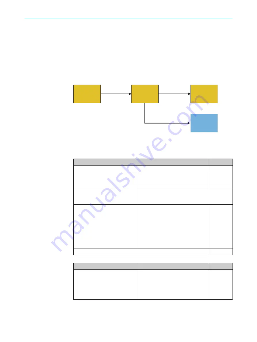
Example response time calculation
Overview
The example calculation includes 2 signal paths. Each signal path needs to be consid‐
ered separately in the calculation.
(IN1)
Digital safety
inputs
(OUT3)
Output to
gateway
CPU
logic,
routing
(OUT1)
Digital safety
outputs
Signal path 1
Signal path 1
Signal path 2
Signal path 2
Robot
deTec4
GPNT
Response time of signal path 1
Table 153: IN1 – Response time of safety capable inputs (I)
When relevant?
Description
Value [ms]
Always
Input processing time
3
ON-OFF debounce filter is configured. Min. debounce filter time
Take the value from the report in the con‐
figuration software.
–
Input element is connected to a test
output (X).
Max. tolerated test pulse delay
Take the value from the report in the con‐
figuration software.
–
Input element is connected to a test
output (X).
•
For safety sensors with a test input or
Flexi Loop: test pulse frequency of the
test output
•
For safety pressure mats: the longer
test pulse frequency of the two test
outputs
•
For electro-mechanical switch/safety
switch (EMSS): test pulse duration of
the test output
–
Total
3
Table 154: OUT1 – Response time of safety outputs (Q)
When relevant?
Description
Value [ms]
When using single-channel safety
output Q.
Potential switch-off delay in the event of a
fault
1)
:
•
Without the
Increased capacitive loads
allowed
option: 5 ms
•
With the
Increased capacitive loads
allowed
option: 50 ms
–
TECHNICAL DATA
13
8024589/2020-11-10 | SICK
O P E R A T I N G I N S T R U C T I O N S | Flexi Compact
135
Subject to change without notice


