6
OPTION
76
OPTI
ON
Chapter
6
-STROBE
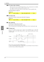
Strobe pulses are output in synchronization with BCD data. Read data using the rising
edges of the pulses. The BCD data output rate setting can be changed.
Example) Negative logic
■
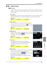
Self check
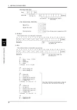
The BCD input / output status can be checked from bit to bit.
Each input turns green when its ON state is recognized.
Each output turns on when the corresponding button is pressed.
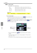
How to set
6-2.
D/A Converter (Option)
A D/A converter is provided for obtaining analog output synchronized with the indicated value of
the DS-6200.
The analog output ranges are -10 - +10V output and 4 - 20mA constant-current output.
By using the D/A zero setting and D/A full scale setting functions, analog output can be obtained
between zero (0V, 4mA) and full scale (10V, 20mA) with respect to the predetermined digital value.
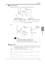
The output circuit and the main unit circuit are isolated. The resolution is 1/10000 to -10 - +10V
and 4 - 20mA, and the conversion rate is 2000 times/sec. The maximum voltage output range are
about
±
11V, the maximum current output range are about 2.4 - 21.6 mA.
BCDdata
OVER
STROBE
Strobe range
0
1
(duty50%)
SET.
Option Setting (BCD OUT)
Page 1
→
→
System Setting
→
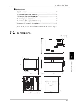
Voltage / current output terminals:
terminals to extract voltage or
current signals.
-10 to +10V and 4 to 20mA can
be obtained by the voltage output
and current output, respectively.
Summary of Contents for DS-6200
Page 1: ......
Page 11: ...CONTENTS 10 M E M O...
Page 12: ...11 11 STANDARD...
Page 13: ...12 12 M E M O...
Page 92: ...91 91 EXPANSION...
Page 93: ...92 92 M E M O...
Page 95: ...Expansion Function 94 M E M O...

