background image

6


STANDARD INTERFACES

133

STA

NDARD INTERFACES

Chapter

6

0

1

2

3

4

5

6

7

8

9

10 11 12 13 14 15 16 17

G S ,

S1

S2 S3 S4 S5 S6 S7

,

1 2 3 . 4 5

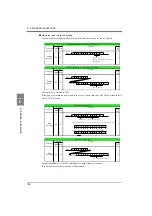
Hold value A

18 19 20 21 22 23 24 25 26 27 28 29 30 31 32 33 34 35

,

1 2 3 . 4 5 ,

1 2 3 . 4 5

Hold value B

Difference value

M:not stable A M:not stable B

H:Hold A

H:Hold B

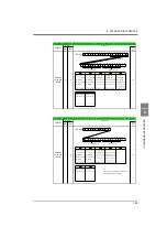
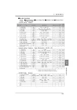
DS-6200

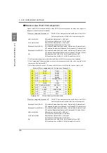
Expansion Double Hold & Before Value Comparison; Continuous transmission/transmission upon printing

Function

Header

Indicated

value and

status

G

S

Main Sub

Compa-

tibility

×

Delimiter

S1

S2

S3

O:Sensor ±Error O:Sensor ±Error

H:HI-A ON

  or ±Over A

  or ±Over B

L:LO-A ON

L:LO-B ON

S:StableA

S:StableB

G:HI-A/LO-A OFF G:HI-B/LO-B OFF

N>(HorL)>F>G

N>(HorL)>F>G

G:Dif.-HI/LO OFF

F:Comparison A OFF F:Comparison B OFF

N:Dif.-HI/LO ON

N:HI-A/LO-A ON N:HI-B/LO-B ON

S6

S7

H>O>(SorM)

H>O>(SorM)

N:Near Zero OFF

A:Zero Tracking OFF

Z:Near Zero ON

T:Zero Tracking ON

O>N>(HorL)>F>G

O:Dif. value ±Over

F:Dif. Comparison OFF

L:Dif.-LO ON

S4

S5

H:Dif.-HI ON

H:HI-B ON

Protocol

0

1

2

3

4

5

6

7

8

9

10

G S ,

S1

S2 S3 S4 S5 S6 S7

,

11 12 13 14 15 16 17 18 19 20 21 22 23 24 25 26 27

1 2 3 . 4 5 ,

1 2 3 . 4 5

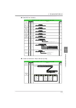
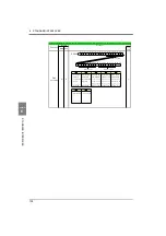
Hold value A(B)*1

Relative Value

M:not stable A M:not stable B

H:Hold A

H:Hold B

*1

DS-6200

Expansion Double Hold & Relative Value Comparison; Continuous transmission/transmission upon printing

Function

Header

Protocol

Main Sub

Compa-

tibility

Indicated

value and

status

G

S

×

Delimiter

S1

S2

S3

S4

S5

O:Sensor ±Error O:Sensor ±Error

H:HI-A(B) ON

O:Relative value ±Over

S:Stable A

S:Stable B

G:HI-A(B)/LO-A(B) OFF

L:Relative-LO ON

  or ±Over A

  or ±Over B

L:LO-A(B) ON

H:Relative-HI ON

N:HI-A(B)/LO-A(B) ON

G:Relative-HI/LO OFF

N>(HorL)>F>G

N:Relative-HI/LO ON

F:Comparison A OFF

N:Near Zero OFF

A:Zero Tracking OFF

Z:Near Zero ON

T:Zero Tracking ON

Insert the value selected by Comparison
Standard in Comparison Setting.

S6

S7

H>O>(SorM)

H>O>(SorM)

F:Rel. Value Comparison OFF

O>N>(HorL)>F>G

Summary of Contents for DS-6200

Page 1: ......

Page 2: ...ction of the ground line For load cell s external input output and option use shielded cables Carefully check wiring etc before applying power Take an interval of more than 5 seconds when repeating ON...

Page 3: ...Caution May explode The means a caution or warning A specific description is written in the The illustration on the left hand side shows a general caution About the built in lithium battery WARNING Mi...

Page 4: ...which is implemented by the European Union EU The Directive restricts the use of six specific substances in electric and electronic equipment handled within EU borders The six substances are lead mer...

Page 5: ...ion 22 RS 232C interface connection 23 Voltage output connection 24 Connecting to cage clamp terminal block 24 3 SETTING PROCEDURE 25 3 1 Screens And Operations 25 Setting modes tree 25 DS 6200 screen...

Page 6: ...limit LO limit HH limit LL limit 43 Hysteresis 43 Near zero 44 Comparison timing 44 Comparison output selection 45 Alarm HI and LO limits 46 5 12 Hold Functions 46 Hold setting Common 46 Hold setting...

Page 7: ...on mode 68 Communication format 69 6 OPTION 73 6 1 BCD Data Output Option 73 Connector pin assignment 73 BCD output data selection 74 BCD output rate 74 Logic switching 74 BCD data hold 74 Equivalent...

Page 8: ...Initialization 84 Work setting protect 84 System setting protect 84 Calibration protect 84 Expansion protect 84 Initialization 84 8 3 Self Check 85 Self check 85 Password 86 8 4 Unit Setting List 86 8...

Page 9: ...son is selected 115 Before value renewal condition 115 Difference HI LO limit comparisons 115 Before value regulation 116 2 2 Before Value Comparison in Double Hold 116 Comparison standard 116 Double...

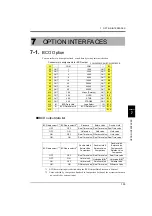
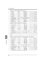
Page 10: ...NTERFACES 128 6 1 SI F 128 6 2 RS 232C 128 7 OPTION INTERFACES 135 7 1 BCO Option 135 BCD output data list 135 7 2 DAV DAI Option 136 8 SUPPLEMENTS 137 8 1 Setting Item List 137 Work setting Compariso...

Page 11: ...CONTENTS 10 M E M O...

Page 12: ...11 11 STANDARD...

Page 13: ...12 12 M E M O...

Page 14: ...eeding the rating or it is used overseas have a suitable AC cable ready separately 1 OUTLINE DIGITAL INDICATOR DIGITAL INDICATOR DIGITAL INDICATOR DIGITAL INDICATOR DIGITAL INDICATOR DIGITAL INDICATOR...

Page 15: ...icator lamp Lamp indication Status Green lighting Steady state Orange lighting Writing into internal NOVRAM Do not turn off the power of the DS 6200 Yellow blink The voltage of the lithium battery for...

Page 16: ...NT or equivalent Signal input output Frame ground Option board AC power input RS 232C connector Analog input output connector connector terminal block mounting slot 7 MONITOR 6 MONITOR 5 SHIELD 4 SIG...

Page 17: ...nal Outputs the RUN signal HOLD END H E Outputs the hold end signal page46 Hold Functions EVENT Outputs the event signal when graph plotting ends COM2 The terminal common to input signals WORK0 WORK1...

Page 18: ...minal block Be sure to ground the F G terminal to prevent electric shocks and failures due to static electricity Optional slot Any one of the following optional boards can be mounted BCD data output D...

Page 19: ...dimensions 2 Remove the screws two and remove the guide rails from both sides Do not use other screws than those installed to the DS 6200 body 3 Fit in the DS 6200 from the front of the panel 4 Insta...

Page 20: ...the cable spread out 1 Make sure that no power is applied 2 Remove the terminal board cover 3 Remove the three screws M3 at the terminal board 4 Align the solderless terminals with the screw holes an...

Page 21: ...ut 5 Tighten the screw with the screwdriver 0 5Nm of tightening torque is recommended 6 Lightly pull the wire to make sure that it is securely clamped 7 Insert the wire connected plug into the DS 6200...

Page 22: ...ernal instruments may be connected A two core parallel cable or a cabtyre cable Wire with covering thickened for construction may be used for connection When a two core parallel cable or a cabtyre cab...

Page 23: ...ing or opening the input terminal and the COM2 terminal Short circuiting is effected by means of a contact such as a relay or a switch or a noncontact such as a transistor or an open collector TTL COM...

Page 24: ...ase two Screw two Pin No Signal name 1 DCD 2 RXD 3 TXD 4 DTR 5 GND 6 DSR 7 RTS 8 CTS Case F G Example of cabling The following shows an example of connection between DTE DTE terminals This will requir...

Page 25: ...clamp system terminal stand Please connect in the following procedure 1 Strip the casing 5 6mm on the cable to be connected 2 Twist the bare wire to fit the terminal hole 3 Insert the supplied screwdr...

Page 26: ...tting PAGE2 Motion Detect P39 Zero Tracking P40 Vol Out Filter P65 Indicate Color P42 B5 Func Select P65 PAGE1 Digital Filter P39 Analog Filter P39 Backlight P41 Language P41 SI F Print Out P41 Contra...

Page 27: ...P85 DSP Check P85 COM Check P86 Calibration PAGE2 Unit P37 Increment P35 Digital Offset P34 DZ Limit P35 PAGE1 Exc Voltage P32 Zero Cal P32 Equiv Cal P33 Actual Cal P33 Cal Select P30 Option Setting...

Page 28: ...S 6200 screen configuration Measurement Setting Back Mode buttons Setting buttons HOME Measurement Back Ordinary display screen Setting menu screen Set value selection screen Set value entry screen Ba...

Page 29: ...his call can be made by the following procedure 1 Press the SET button on the ordinary display screen 2 The setting menu screen appears Select the item 3 The setting function setting screen appears Se...

Page 30: ...actual load is available For example the gain is automatically determined by entering 2 001mV V rated output 100 0kg capacity Actual load calibration Apply an actual load to the strain gage sensor and...

Page 31: ...cording to the input conditions of external signal inputs CAL0 and CAL1 the display changes as EXT 0 to EXT 3 Normally when there is no input to CAL0 and CAL1 the terminals are open calibration value...

Page 32: ...Calibration Enter the rated output value and reading of the strain gage sensor At this time also input the decimal point Actual Load Calibration Enter the span gain point of the strain gage sensor wit...

Page 33: ...can be selected from 2 5V and 10V After this setting be sure to perform calibration How to set 4 4 Zero Calibration Set the zero point in no load condition How to set 1 Press the SET button 2 Press th...

Page 34: ...al point key at the end 4 6 Equivalent Input Calibration Set the rated output value and reading of the sensor Rated output value 3 000 3 000mV V 0 is excluded Display value 99999 99999 0 is excluded H...

Page 35: ...ent when zero cannot be obtained with no load for some reason or for offsetting When not using set 0 Displayed value Actual indicated value Offset value How to set 1 Press the SET button refer to page...

Page 36: ...e Calibration button refer to page 32 3 Select page 2 and press the DZ Limit button 4 Enter the digital zero limit value by the numerical keys and determine with the OK button 4 9 Increment This step...

Page 37: ...that they will not be changed by misoperation When Cal Protect is ON no change can be made while the alarm sounds ON Protected OFF Unprotected How to set 1 Press the SET button refer to page 32 2 Pre...

Page 38: ...w to set 1 Press the SET button refer to page 32 2 Press the Calibration button refer to page 32 3 Select page 2 and press the Unit button 4 First select the category and then select the unit and dete...

Page 39: ...formed by short circuiting the D Z to the COM2 on the rear panel signal I O terminal block 5 SETTING OF FUNCTIONS YES NO D Z OFF ON Keep on for 1 0 msec or more CAUTION When digital zero is performed...

Page 40: ...se components may be indicated Cut off frequency 30Hz 100Hz 300Hz 1000Hz How to set 5 4 Motion Detect MD Enter the parameters to detect stable If the difference between the current indicated value and...

Page 41: ...zero by Zero Tracking function The time tracking delay is set in the range of 0 1 9 9 sec and the band tracking band is set in the range of 01 to 99 If the time is set at 0 0 sec and the band at 00 th...

Page 42: ...stable Set the stable parameters by the Motion Detect When Near Zero is OFF Indicated value is held until Near Zero turns ON after stable turned ON Hold will be released when 1 5 sec is passed after N...

Page 43: ...es are set and when the indicated value exceeds the HI limit the HI output is turned on and when the indicated value falls below the LO limit the LO output is turned on Also HH limit and LL limit valu...

Page 44: ...e subtly Comparison conditions HI limit ON condition indicated value HI limit value OFF condition indicated value HI limit value hysteresis value LO limit ON condition indicated value LO limit value O...

Page 45: ...alue is not near zero Set the near zero parameters by the near zero operation MD NZ HI LO limit comparison is performed when the indicated value is stable and not near zero HOLD HI LO limit comparison...

Page 46: ...LL H1 L3 HI LO 1 OK LO 2 LO 3 H0 L4 LO 1 LO 2 OK LO 3 LO 4 Mode HI limit operation LO limit operation H4 L0 HI 1 to HI 4 None H3 L1 HI 1 to HI 3 LO H2 L2 HH HI LO LL H1 L3 HI LO 1 to LO 3 H0 L4 None L...

Page 47: ...on Hold mode The DS 6200 includes 10 hold modes as shown in the table below In the peak valley peak to peak and average modes section setting is required Select all section external signal external si...

Page 48: ...the hold stop level in the case where the Section setting is Level for Peak or Valley hold Setting range 99999 99999 How to set Detection start condition Setting range Ext Level Ext Only How to set Si...

Page 49: ...when the load exceeds difference X multiplied by the relative magnification 1 4 to 4 A B and the difference between A and B are held in relative maximum hold relative minimum hold and relative differe...

Page 50: ...ated value over A from the amount of change of the indicated value over B is D when the amount of change D exceeds the inflection minimum slope point a is held as an inflection point If there are two...

Page 51: ...nflection rear sope time to the inflection minimum slope In the example set load change D 80 obtained by subtracting load C 10 changing with A from load 90 changing with B to the inflection minimum sl...

Page 52: ...point is held and the H E output is turned on Hold of the value continues as long as the T H signal is on t1 A delay time between the instant when the T H signal is inputted and the instant when the...

Page 53: ...time level time or level Example All section valley hold t1 A delay time between the instant when the T H signal is inputted and the instant when the indicated value is held 1 0ms max t2 A delay time...

Page 54: ...n operation The section is specified by the setting of all section external signal external signal time or level time Example Externally specified section average value hold t1 A delay time between th...

Page 55: ...min Relative maximum Relative minimum Relative difference hold The way of starting detection is the same as Inflection Point hold Example Relative maximum hold t1 A delay time between the instant whe...

Page 56: ...the SECTION signal to maintain the hold value until the reset signal is turned on The hold is released by turning on the T H signal as a reset signal The H E output signal is on between the instant wh...

Page 57: ...on the T H signal as a reset signal The H E output signal is on between the instant when the hold section time ends and the instant when the T H signal is turned on Example Level Time specified secti...

Page 58: ...d 1 0ms min 5 13 Multi hold Function By this function up to 16 types of hold graph and comparison set values can be stored and selected with external switching signals of WORK0 WORK3 Normally if there...

Page 59: ...ORK1 B4 WORK2 B5 WORK3 CAUTION It takes 15msec at the maximum for the changed work No to become effective During this section which work is measured is undefined Also when the work is switched the hol...

Page 60: ...232C becomes effective EXT Control by communication RS 232C becomes ineffective and only control by external input becomes effective How to set 5 16 B6 OFF Detection Wait In hold controlled by the TH...

Page 61: ...ld point plotting By using the hold function and the graph plotting function together the held point red can be plotted SET Operation Page 3 System Setting X axis time axis Graphic display START STOP...

Page 62: ...are plotted Y axis The Y axis is a load setting value A graph is plotted between the Y start point and the Y end point There are 100 plotting points Graph plotting Continued Graph plotting starts wit...

Page 63: ...h Start Level Passed HI External level Plotting starts when the Level Condition is met in comparison of the Graph Start Level and indicated value after GRAPH TRIG external input ON Plotting ends on on...

Page 64: ...ition If you select level or external level in the graph function setting set the graph plotting start level comparison conditions Setting range Passed Passed HI Passed LO Beyond Below How to set SET...

Page 65: ...Simple setting call Press the X button on the graph display to go direct to the X end point entry screen SET Graph Setting Page 1 Work Setting Simple setting call Press the Y button on the graph displ...

Page 66: ...verter Voltage output filter Whether to extract the voltage output before or after the internal analog filter can be switched ON Output after the analog filter OFF Output before the analog filter How...

Page 67: ...al zero limit error RUN out specifications are as follows RUN output spec Normally the signal repeating ON OFF operation is output CAUTION By the selection of each LOCK function measurement work that...

Page 68: ...fications Signal level Based on RS 232C Transmitting distance Approx 15m Transmitting method Asynchronous Full duplex Transmitting speed 9600 19200 38400 or 57600 bps Selectable Bit configuration Star...

Page 69: ...ormal Communications are carried out by commands from the host computer The indicated value status and parameters can be read and parameters can be written 2 Continue The indicated value and status ar...

Page 70: ...ted value has no decimal point a decimal point follows the numerical value Host DS 6200 R D CR R D 0 0 0 0 0 0 0 1 ON 0 OFF 1 ON 0 OFF Near Zero 1 ON Output signal 0 OFF HI 1 ON Output signal 0 OFF LO...

Page 71: ...rotect Work Setting Protect Work Setting Protect Work Setting Protect Work Setting Protect Work Setting Protect CR LF 1 2 W 0 0 0 0 CR LF 2 2 W 0 0 CR LF 3 2 W CR LF 4 2 W 0 CR LF 5 2 W 0 0 0 0 0 CR L...

Page 72: ...assed 0 Cal 0 1 Ext 1 Passed HI 1 Cal 1 2 Level 2 Passed LO 2 Cal 2 3 Ext Level 3 Beyond 3 Cal 3 4 Below 4 EXT Set value correspondence table Host DS 6200 G R CR Decimal Point and Five digits Data1 00...

Page 73: ...G 4 H HH limit ON L LL limit ON G HH limit and LL limit OFF N HH limit and LL limit ON F Compare OFF 4 Priority N H or L F G 5 N Near Zero OFF Z Near Zero ON Host DS 6200 CR Set Value No The same for...

Page 74: ...atible connector FCN 361J032 AU manufactured by FUJITSU COMPONENT or equivalent Connector cover FCN 360C032 B manufactured by FUJITSU COMPONENT or equivalent No Signal No Signal A1 COM B1 COM A2 OUT 1...

Page 75: ...er inputting the logic switching When COM and pin B14 are open negative logic When they are short circuited positive logic BCD data hold Renewal of the BCD data output signal is stopped Also the STROB...

Page 76: ...e time of a sensor error or OVER DS 6200 Inside Vcc 5V COM Vext Vceo 30V max Ic 30mA max Output data Negative Positive 0 OFF ON 1 ON OFF Output data Negative Positive 0 1 Through logic switching B14 O...

Page 77: ...nges are 10 10V output and 4 20mA constant current output By using the D A zero setting and D A full scale setting functions analog output can be obtained between zero 0V 4mA and full scale 10V 20mA w...

Page 78: ...nge 99999 99999 where zero set value full scale set value In the case of voltage output Zero scale Set the indicated value for the time of output of 0V Full scale Set the indicated value for the time...

Page 79: ...nt screen to adjust the output While monitoring the output value make fine adjustment of the output with the UP DOWN button of the simulated trimmer and determine by pressing the button so that the tr...

Page 80: ...age output Output level Approx 2V per 1mV V of input Load Load resistance 2k or more Digital section Display STN color LCD module display area 71mm 53mm 320 240 dots Indicated value 99999 5 digit Equi...

Page 81: ...linearity 0 05 FS Response Dependent on the A D conversion speed 2000 times sec of the main unit External input and output Output HI LO limit comparison output HH HI OK LO LL Normal operation output...

Page 82: ...t connector 1 AC input cord with solderless terminal 1 Conversion plug for AC input code 1 Connector for BCD output with BCD option 1 Mini screwdriver with DAV DAI option 1 The attached AC input cord...

Page 83: ...NOV RAM 4096bit Input T H DZ WORK0 3 SECTION GRAPH TRIG 10 Line SI F HI HH OK H E RUN EVENT SIF MPU Touch LCD LCD D A BCD LO LL 5VI 12VI 9VA 5VD F G FRAME Power Supply Unit 9VA Option MONITOR Buffer...

Page 84: ...en the real time value sensor input value exceeds the alarm HI limit or drops below the alarm LO limit Check the sensor for excessive load Zero error Zero calibration error This message indicates that...

Page 85: ...Expansion protect Set whether to protect the set values in Expansion Setting from changing Setting range ON OFF How to set Initialization All the set values of each setting item are initialized to the...

Page 86: ...es the previous screen How to set MEM check Check the memory to see that it is free from defects The result is displayed in a moment after the at the lower right of the screen is pressed Or check the...

Page 87: ...m the cable or the setting of communication condition when it is not possible to confirm it Password This setting is for maintenance and inspection Do not operate 8 4 Unit Setting List The numbers cor...

Page 88: ...Alarm LO Limit 99999 99999 to 99999 S 8 Near Zero 100 0 to 99999 S 9 Comparison Timing 0 ALL 0 ALL 1 MD 2 NZ 3 MD NZ 4 HOLD S 10 Comparison Output Selection 2 H2 L2 1 S Page No Item Initial value Sett...

Page 89: ...h Mode 0 Continued 0 Continued 1 Ext 2 Level 3 Ext Level S 2 Y LD Start Point 0 99999 to 99999 S 3 Y LD End Point 10000 99999 to 99999 S 4 X TM End Point 10 0 sec 0 1 to 99 9 sec S 5 Graph Start Level...

Page 90: ...ory Protect 1 1 Digital Filter OFF 0 OFF 2 to 999 Times N 2 Analog Filter 2 300Hz 0 30 1 100 2 300 3 1000 Hz N 3 Backlight 10 Min 0 to 99 Min Always lighting when 0 N 4 Language 0 JPN 0 JPN 1 ENG N 5...

Page 91: ...500 6 1000 7 2000 s N 3 4 5 1 1 Output Select 1 Hold 0 Real Time 1 Hold 2 Zero Scale 4 Full Scale N 2 3 Zero Scale 0 99999 to 99999 N 4 Full Scale 10000 99999 to 99999 N 5 Scale Set Select 0 0 to 3 N...

Page 92: ...91 91 EXPANSION...

Page 93: ...92 92 M E M O...

Page 94: ...gger Selection P108 Hold Off On Digital Zero P111 Hold End Timing P113 Expansion Graph Setting Pre Trigger Display P124 Expansion Operation Setting Digital Filter Character P125 Average Time On Digita...

Page 95: ...Expansion Function 94 M E M O...

Page 96: ...ne 7 Relative Maximum None None 8 Relative Minimum None None 9 Relative Difference None None 10 Sample Peak Section select 2 11 Sample Valley Section select 2 12 Sample P P Section select 2 13 Sample...

Page 97: ...etting Hold operations For the operations of the HOLD buttons and HI LO Limit judgment outputs see the DS 6200 Operation Manual Standard 1 A Sample hold B None An arbitrary point is held when the SECT...

Page 98: ...setting is External Sensor Input Value Hold Value B Hold Value A Status Display Status Display Status Display Status Display HOLD B OFF PEAK A OFF OFF OFF Blink ON HOLD A OFF ON B OFF SECTION T H H E...

Page 99: ...When the Section setting is External Sensor Input Value Hold Value B Hold Value A Status Display Status Display Status Display Status Display B OFF HOLD B OFF OFF P P A OFF Blink ON OFF ON HOLD A OFF...

Page 100: ...Only Sensor Input Value Hold Value B Hold Value A SECTION T H H E HOLD A OFF OFF Status Display Blink ON Status Display Status Display B OFF Hold Start Level ON OFF OFF INF A HOLD B OFF Status Displa...

Page 101: ...SECTION signal is ON The minimum value in the section specified is held The value is maintained until the T H signal turns ON Sensor Input Value Hold Value B Hold Value A Status Display Status Displa...

Page 102: ...ary point is held when the SECTION signal is ON The averageof the section specified is held The value is maintained until the T H signal turns ON Sensor Input Value Hold Value A Hold Value B Status Di...

Page 103: ...urns ON with the hold Detection Start Condition External Only The value is maintained until the T H signal turns ON When the Detection Start Condition is External Only Sensor Input Value Hold Value A...

Page 104: ...the SECTION signal are held The value is maintained until the T H signal turns ON When the Section setting is External Hold Value A Sensor Input Value Hold Value B Status Display Status Display Status...

Page 105: ...section specified by the SECTION signal are held The value is maintained until the T H signal turns ON When the Section setting is External Sensor Input Value Hold Value B Hold Value A Status Display...

Page 106: ...nimum value in the section specified by the SECTION signal are held The value is maintained until the T H signal turns ON Sensor Input Value Hold Value A Hold Value B Status Display Status Display OFF...

Page 107: ...the Detection Start Condition is External Only Sensor Input Value Hold Value A Hold Value B SECTION T H H E OFF Status Display MIN B Status Display Blink ON OFF OFF OFF HOLD B OFF ON Status Display O...

Page 108: ...HI B ON Condition Hold B HI B OFF Condition Hold B HI B LO B ON Condition Hold B LO B OFF Condition Hold B LO B OK ON Condition All of HI A HI B LO A and LO B are OFF OFF Condition Any of HI A LO A HI...

Page 109: ...HOLD END H E SECTION IN B8 A9 Out RUN DIGITAL ZERO IN B9 A10 Out EVENT GRAPH TRIG IN B10 A11 Out SIF CAL0 IN B11 A12 Out SIF CAL1 IN B12 External I O pin assignments for Double Hold Sensor Input Valu...

Page 110: ...edge operation where the hold modes are A Sample hold B Inflection Point When the Detection Start Condition is External Only Sensor Input Value Hold Value A Hold Value B Blink Blink ON A OFF HOLD B OF...

Page 111: ...H SECTION Upon turning ON of the SECTION signal hold reset is performed and detection starts Control can be performed without inputting the T H signal However a hold value is maintained until the SECT...

Page 112: ...d modes are A Sample hold B Inflection Point hold SET Hold Setting Page 1 Work Setting CAUTION The sample hold with double hold OFF is controlled simply by the T H signal when auto reset is ON but con...

Page 113: ...ld Section ends the hold value is renewed This is however effective only when Hold Auto Reset is ON In the case of Peak hold SET Exp Hold Set Page 1 Exp Setting H E SECTION T H Hold Start Level Sectio...

Page 114: ...iming in which the SECTION signal is off Detect Sct HOLD END H E is on immediately after the detection of the hold point Hold operations SET Exp Hold Set Page 2 Exp Setting In the case of Inf ection P...

Page 115: ...ue Present hold value indicated value Previous hold value In the case of Peak hold The comparison output in the above timing chart applies to the case where the Comparison Timing setting in Comparison...

Page 116: ...I Limit 99999 99999 Initial value 1000 Difference LO Limit 99999 99999 Initial value 1000 When Before Value Comparison is made judgments are made under the following conditions and respective results...

Page 117: ...screens in double hold appear Also the Comparison Setting menu is dedicated Comparison standard In double hold Before Value Comparison can be made only on either A or B by selecting either Hold A or...

Page 118: ...comparison result of the value targeted for the Comparison Timing turns OFF OK is displayed each on the LCD screen as hold value A and the difference value are OK and hold value B is OK When the Comp...

Page 119: ...value can be made In the case of Comparison Standard A where Hold A Sample Hold B Inflection Point The comparison output in the timing chart shown on the right hand side applies to the case where the...

Page 120: ...d value A and hold value B Relative HI 99999 99999 Initial value 1000 Relative LO 99999 99999 Initial value 1000 Comparison standard Relative Value Comparison is made by selecting either of Hold A and...

Page 121: ...t met the comparison result of the value targeted for the Comparison Timing turns OFF OK is displayed each on the LCD screen as hold value A is OK and the relative value is OK When the Comparison Stan...

Page 122: ...measurement screens appear Also the Comparison Setting menu is dedicated Difference and relative HI LO limit comparisons HI LO Limit Difference HI LO and Relative HI LO Limit comparisons of Double Ho...

Page 123: ...the Comparison Standard is B The HI LO Limit comparison result of the relative value and the HI LO Limit comparison result and Difference HI LO Limit comparison result of hold value B are output toget...

Page 124: ...is displayed each on the LCD screen as the relative value is OK and hold value B and the difference value are OK FCN 365P024 AU FCN 360C024 B Extyernal I O A1 COM1 COM2 B1 A2 OUT HI B DF HI WORK0 IN B...

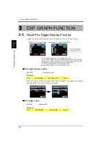
Page 125: ...nitial value 0 How to set 3 EXP GRAPH FUNCTION Absence of Pre Trigger Display Presence of Pre Trigger Display 20 The Pre Trigger Value can be set in the range of 0 to 20 Even if the Pre Trigger Value...

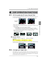
Page 126: ...characteristics is small A high pass filter can also be selected Digital filter character STANDARD CR type LPF CR type HPF Initial value STANDARD How to set When this setting is CR type LPF or CR typ...

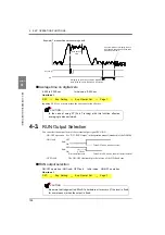
Page 127: ...ON OFF operation How to set I Example Time specified section average hold Averaging by the Average Time On Digital Zero Upon completion of averaging the ave Hold Section Time Section 1 rage result is...

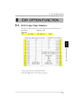
Page 128: ...SET Exp Option Set Page 1 Exp Setting A1 COM COM B1 A2 OUT 20 212 OUT B2 A3 OUT 21 213 OUT B3 A4 OUT 22 214 OUT B4 A5 OUT 23 215 OUT B5 A6 OUT 24 216 OUT B6 A7 OUT 25 OUT B7 A8 OUT 26 BCD Data Select...

Page 129: ...value B Double Hold Before Value Comparison Difference value Hold value B A Hold value A Difference value B Double Hold Relative Value Comparison Hold value A Relative value A Relative value Hold val...

Page 130: ...000 199 In P P hold for example two points are displayed therefore information of those two points can be read The above shows the case of Hold A When there is no data graph data and indicated value a...

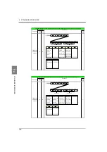
Page 131: ...tocol Main Sub Compa tibility A Host Delimiter A 0 0 0 1 CR DS 6200 A 0 0 0 1 0 0 0 0 1 2 Work no 00 16 Setting work no A Function Header Main Sub Host Protocol Compa tibility Delimiter Expansion Work...

Page 132: ...o C G Standard Continuous transmission transmission upon printing Function Header Protocol Main Sub Compa tibility Numerical values other than the above are ignored 0 1 2 3 4 5 6 7 8 9 10 11 12 G S S...

Page 133: ...LO OFF F Comparison OFF H O orM N Near Zero OFF Zero Tracking OFF Z Near Zero ON Zero Tracking ON O N HorL F G 0 1 2 3 4 5 6 7 8 9 10 G S S S2 S3 S4 S5 S6 S7 11 12 13 14 15 16 17 18 19 20 21 22 23 24...

Page 134: ...OFF Z Near Zero ON Zero Tracking ON O N HorL F G O Dif value Over F Dif Comparison OFF L Dif LO ON H Dif HI ON H HI B ON Protocol 0 1 2 3 4 5 6 7 8 9 10 G S S S2 S3 S4 S5 S6 S7 11 12 13 14 15 16 17 1...

Page 135: ...F Comparison A B OFF F Rel Value Comparison OFF L Dif LO ON not stable A not stable B G HI A B LO A B OFF G Relative HI LO OFF G Dif HI LO OFF Stable A Stable B L LO A B ON L Relative LO ON Compa tibi...

Page 136: ...BCD data select 0 1 Double Hold Before Value Comparison Double Hold Relative Value Comparison Double Hold Before Value Comparison Relative Value Comparison OFF OFF Real Time value Real Time value Real...

Page 137: ...ERFACES Chapter 7 7 2 DAV DAI Option At standard time you can select real time value or hold value At expansion Double Hold time you can select real time value hold value A or hold value B Before Valu...

Page 138: ...Selection 2 H2 L2 0 H4 L0 1 H3 L1 2 H2 L2 3 H1 L3 4 H0 L4 S 110 R W 1 1 HI Limit 6000 99999 to 99999 S 101 R W 2 LO Limit 4000 99999 to 99999 S 102 R W 3 Difference HI Limit 1000 99999 to 99999 S 111...

Page 139: ...2 104 R W 3 Relative HI Limit 1000 99999 to 99999 S 117 R W 4 Relative LO Limit 1000 99999 to 99999 S 118 R W 5 Hysteresis 0 9999 to 9999 S 105 R W 2 6 Alarm HI Limit 99999 99999 to 99999 S 106 R W 7...

Page 140: ...Passed LO S 204 R W 5 Hold Auto Reset 1 ON 0 OFF 1 ON S 205 R W Hold Section Command No 0 All 216 1 EXT 2 EXT TM 3 LVL TM 4 LVL HoldA HoldB 0 OFF OFF 1 Sample OFF 2 Peak OFF 3 Valley OFF 4 P P OFF 5 A...

Page 141: ...ger select Average hold 2 6 Sample Removal Value 0 999 to 999 S 206 R W 7 8 9 10 2 6 Sample Removal Value 0 999 to 999 S 206 R W 7 Sample Trigger Select 1 0 ON Edge 0 ON Edge 1 OFF Edge S 217 R W 8 9...

Page 142: ...30 1 to 99999 S 209 R W 12 Inflection Front Slope Time 200 10 to 990 Front slope time rear slope time 1000 S 210 R W 13 Inflection Rear Slope Time 200 10 to 990 Front slope time rear slope time 1000...

Page 143: ...3 R W 9 10 2 6 Sample Removal Value 0 999 to 999 S 206 R W 7 8 9 10 3 11 Relative Minimum Count 10 1 to 99999 S 214 R W 12 Relative magnification 3 1 00 4 S 215 R W 13 Detection Start Condition 0 Ext...

Page 144: ...5 Graph Start Level 100 99999 to 99999 S 305 R W 2 6 Interval Time 1 00 sec 0 0 to 99 9 sec S 306 R W 7 Level Condition 1 Passed HI 0 Passed 1 Passed HI 2 Passed LO 3 Beyond 4 Below S 307 R W 8 9 10 3...

Page 145: ...excluded N 2004 R W 5 Calibration Selecttion 0 Cal 0 0 Cal 0 1 Cal 1 2 Cal 2 3 Cal 3 4 EXT 0 N 2005 R W 2 6 Unit kN 2 N 2006 R W 7 Increment 0 1 0 1 1 2 2 5 3 10 4 20 5 50 6 100 N 2007 R W 8 Digital O...

Page 146: ...t Wait 0 00 sec 0 00 to 1 00 sec N 514 R W 13 Measurement work selection 1 EXT 0 COM 1 EXT N 515 R W 14 Control input selection 1 EXT 0 COM 1 EXT N 516 R W 15 Password 1 1 Digital Filter 1Hz 1 to 990H...

Page 147: ...Dif 3 EXT N 701 R 2 BCD Output Rate 3 100 s 0 10 1 20 2 50 3 100 4 200 5 500 6 1000 7 2000 s N 702 R 3 4 5 1 1 BCD Output Select 1 HoldA 0 Realtime 1 HoldA 2 HoldB 3 EXT N 701 R 2 BCD Output Rate 3 1...

Page 148: ...ibration Protect 0 OFF 0 OFF 1 ON N 4003 R 4 Expansion Protect 1 ON 0 OFF 1 ON N 4004 R 5 Initialization 0 Work Set 0 Work Set 1 Sys Set 2 Cal Set 3 Exp Set Page No Item Initial value Setting range Me...

Page 149: ...le Trigger Selection 0 OFF 0 OFF 1 ON N 3104 R 5 Hold Off On Digital Zero 0 OFF 0 OFF 1 ON N 3105 R 2 6 Hold End Timing 1 Detect Sct 0 Hold Sct 1 Detect Sct N 3106 R 1 1 Pre Trigger Display 0 OFF 0 OF...

Page 150: ...58 3241 Fax 03 3859 1240 Tel 03 3850 5431 Fax 03 3850 5436 1 5 16 ENOKOJIMA NISI KU OSAKA 550 0006 JAPAN 5 24 27 HOKIMA ADATI KU TOKYO 121 0064 JAPAN 1 17 16 NISHI HOKIMA ADATI KU TOKYO 121 0812 JAPAN...

Reviews: