


86(142)
5
Error Connection
Error
Caused
Troubleshooting
Alarm No. E001
The main control board
error.
Main control action error.
Please turn off the power supply and
restart system. If still alarming, please
contact with manufacture.
Alarm No. E002
Data access error.
System memory access
error.
Please turn off the power supply and
restart system. If still alarming, please
contact with manufacture.
Alarm No. E003
Low air pressure.
Robot air low pressure.
Robot working in low air pressure is not
safety. Please check air pressure, press
“
Reference
”
key to resume normal value
(4-5kg).
Alarm No. E004
Servo not ready.
Servo driver error.
Robot servo driver not ready. Please
check and restart it.
Alarm No. E005
Servo alarm.
Robot servo driver alarm.
Please check servo driver. After
troubleshooting, please restart servo
driver.
Alarm No. E006
Robot traverse limit.
Robot arm moves to
traveser limit position.
Turn off system and check servo driver.
Move robot arm out of limit position and
restart system.
Alarm No. E007
Servo position not safety
when robot arm down.
Servo alarm, mold safety
signal off.
Please check the servo motor and mold
safety signal.
Alarm No. E008
Hand controller emergency
stop.
The emergency stop button
on hand controller is
pressed.
Release emergency stop button and
press
“
Reference
”
key.
Alarm No. E009
IMM emergency stop.
The emergency stop button
of IMM is pressed.
Release emergency stop button and
press
“
Reference
”
key on hand
controller, check the wirings connection.
Alarm No. E010
Production plan finished.
Robot in auto mode, the
picked up products reached
the setting numbers.
Please press
“
Reference
”
key into
manual mode to continue running.
Alarm No. E011
Reject exceeded.
Robot in auto mode, the
reject exceeded the setting
numbers.
Please press
“
Reference
”
key into
manual mode and check IMM
production.
Alarm No. E012
Undefined
Undefined
Alarm No. E013
Main arm forward error.
When robot main arm
forward with backward
signal.
Please check the cylinder, valve and
sensor. After troubleshooting, press
“
Reference
”
key.
Alarm No. E014
Main arm backward error.
When robot main arm
backward with forward
signal.
Please check the cylinder, valve and
sensor. After troubleshooting, press
“
Reference
”
key.
Alarm No. E015
Main arm horizontal error.
When robot main arm
horizontal with vertical
signal.
Please check the cylinder, valve and
sensor. After troubleshooting, press
“
Reference
”
key.
Alarm No. E016
Main arm vertical error.
When robot main arm
vertical with horizontal
signal.
Please check the flip cylinder, valve and
sensor. After troubleshooting, press
“
Reference
”
key.
Summary of Contents for ST1-S
Page 1: ...ST1 S User Manual Date May 2016 Vision V1 0 English ...
Page 2: ......
Page 10: ...10 142 ...
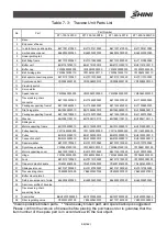
Page 94: ...94 142 7 Assembly Diagram 7 1 Traverse Unit ST1 S and ST1 T S Picture 7 1 ...
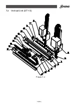
Page 99: ...99 142 7 2 Vertical Unit ST1 S Picture 7 2 ...
Page 102: ...102 142 7 3 Main Arm Unit ST1 S Picture 7 3 ...
Page 105: ...105 142 7 4 Sub arm Unit ST1 S Picture 7 4 ...
Page 108: ...108 142 7 5 Main Arm ST1 T S Picture 7 5 ...
Page 110: ...110 142 7 6 Sub arm ST1 T S Picture 7 6 ...
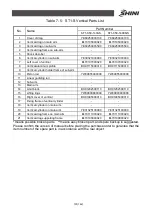
Page 113: ...113 142 7 7 Vertical ST1 T S Picture 7 7 ...
Page 115: ...115 142 7 8 Traverse Unit ST1 T S Middle Telescopic Arm Picture 7 8 ...
Page 119: ...119 142 7 9 Main Arm ST1 T S Middel Telescopic Arm Picture 7 9 ...
Page 123: ...123 142 7 10 Sub arm ST1 T S Middel Telescopic Arm Picture 7 10 ...
Page 127: ...127 142 7 11 Crosswise Unit ST1 T S Middle Telescopic Arm Picture 7 11 ...
Page 131: ...131 142 8 1 2 The Panasonic Servo Motor and Servo Driver Wiring Diagram Picture 8 2 ...
Page 132: ...132 142 8 1 3 The Panasonic Servo Motor and I O Board Wiring Diagram Picture 8 3 ...
Page 133: ...133 142 8 1 4 The Delta Servo Motor and Servo Driver Wiring Diagram Picture 8 4 ...
Page 134: ...134 142 8 1 5 The Delta Servo Motor and I O Board Wiring Diagram Picture 8 5 ...
Page 135: ...135 142 8 1 6 The Cuinsico Servo Motor and Servo Driver Wiring Diagram Picture 8 6 ...
Page 136: ...136 142 8 1 7 The Cuinsico Servo Motor and I O Board Wiring Diagram Picture 8 7 ...
Page 137: ...137 142 8 1 8 Z axis I O Board Wiring Diagram Picture 8 8 ...
Page 138: ...138 142 8 1 9 Main Arm Wiring Diagram Picture 8 9 ...
Page 139: ...139 142 8 1 10 Sub arm Wiring Diagram Picture 8 10 ...
Page 140: ...140 142 8 1 11 Main Arm Output Wirng Diagram Picture 8 11 ...
Page 141: ...141 142 8 1 12 Signals Input Wiring Diagram Picture 8 12 ...
Page 142: ...142 142 8 1 13 Signals Output Wiring Diagram Picture 8 13 ...


