


103(142)
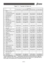
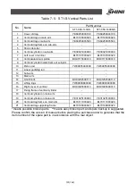
7.3.1 Parts List
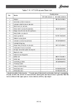
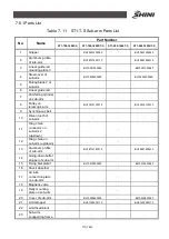
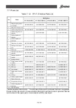
Table 7- 6
:
ST1-S Main Arm Parts List
Parts Number
No.
Name
ST1-650-1200-S
ST1-650-1200D-S
ST1-750-1300-S
ST1-750-1300D-S
1
Rotation board
BH10550900020
BH10550900020
BH10550900020
BH10550900020
2
Spare frame for air pipe
BL70102600020
BL70102600020
BL70102600020
BL70102600020
3
Steel covers of main arm
-
-
-
-
4
Aluminum cover
of main arm
-
-
-
-
5
Drag chain on main arm
(up/down)
YE60250003700
YE60250003700
YE60250003700
YE60250003700
6
Drag chian connector on
main arm
BL70108000020
BL70108000020
BL70108000020
BL70108000020
7
Down baffle on main arm
-
-
-
-
8
Main arm aluminum
profile
-
-
-
-
9
Linear guiding rail
-
-
-
-
10
Cylinder on main arm
(up/down)
YE30326700000
YE30326700000
YE30325700000
YE30325700000
11
Shock absorber
YW10255020000
YW10255020000
YW10255020000
YW10255020000
12
Silencer sleeve 20
YW80200000000
YW80200000000
YW80200000000
YW80200000000
13
Air pipe connection plate
on main arm
-
-
-
-
14
Connection cover of main
arm
-
-
-
-
15
Digital display pressure
switch
YW80204050000
YW80204050000
YW80204050000
YW80204050000
16
Relay mounting plate on
main arm
-
-
-
-
17
Pneumatinc distribution
block on main arm
-
-
-
-
18
Magnetic valve
-
-
-
-
19
Main arm mounting plate
-
-
-
-
20
Buffer unit
BH91181200010
BH91181200010
BH91181200010
BH91181200010
21
Buffer cap
YW80200000000
YW80200000000
YW80200000000
YW80200000000
22
Falling-proof cylinder
YE30055000350
YE30055000350
YE30055000350
YE30055000350
23
Proximity switch
-
-
-
-
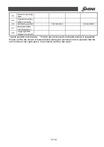
24
Mian arm supporting
frame
-
-
-
-
25
Mian arm falling-proof
stop plate
-
-
-
-
26
Cylinder holder frame on
main arm
-
-
-
-
*means possible broken parts. **means easy broken part, and spare backup is suggested.
Please confirm the version of manual before placing the purchase order to gurantee that the
item number of the spare part is in accordance with the real object.
Summary of Contents for ST1-S
Page 1: ...ST1 S User Manual Date May 2016 Vision V1 0 English ...
Page 2: ......
Page 10: ...10 142 ...
Page 94: ...94 142 7 Assembly Diagram 7 1 Traverse Unit ST1 S and ST1 T S Picture 7 1 ...
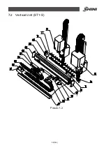
Page 99: ...99 142 7 2 Vertical Unit ST1 S Picture 7 2 ...
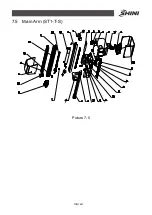
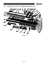
Page 102: ...102 142 7 3 Main Arm Unit ST1 S Picture 7 3 ...
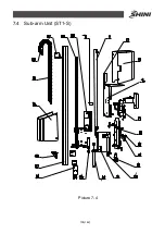
Page 105: ...105 142 7 4 Sub arm Unit ST1 S Picture 7 4 ...
Page 108: ...108 142 7 5 Main Arm ST1 T S Picture 7 5 ...
Page 110: ...110 142 7 6 Sub arm ST1 T S Picture 7 6 ...
Page 113: ...113 142 7 7 Vertical ST1 T S Picture 7 7 ...
Page 115: ...115 142 7 8 Traverse Unit ST1 T S Middle Telescopic Arm Picture 7 8 ...
Page 119: ...119 142 7 9 Main Arm ST1 T S Middel Telescopic Arm Picture 7 9 ...
Page 123: ...123 142 7 10 Sub arm ST1 T S Middel Telescopic Arm Picture 7 10 ...
Page 127: ...127 142 7 11 Crosswise Unit ST1 T S Middle Telescopic Arm Picture 7 11 ...
Page 131: ...131 142 8 1 2 The Panasonic Servo Motor and Servo Driver Wiring Diagram Picture 8 2 ...
Page 132: ...132 142 8 1 3 The Panasonic Servo Motor and I O Board Wiring Diagram Picture 8 3 ...
Page 133: ...133 142 8 1 4 The Delta Servo Motor and Servo Driver Wiring Diagram Picture 8 4 ...
Page 134: ...134 142 8 1 5 The Delta Servo Motor and I O Board Wiring Diagram Picture 8 5 ...
Page 135: ...135 142 8 1 6 The Cuinsico Servo Motor and Servo Driver Wiring Diagram Picture 8 6 ...
Page 136: ...136 142 8 1 7 The Cuinsico Servo Motor and I O Board Wiring Diagram Picture 8 7 ...
Page 137: ...137 142 8 1 8 Z axis I O Board Wiring Diagram Picture 8 8 ...
Page 138: ...138 142 8 1 9 Main Arm Wiring Diagram Picture 8 9 ...
Page 139: ...139 142 8 1 10 Sub arm Wiring Diagram Picture 8 10 ...
Page 140: ...140 142 8 1 11 Main Arm Output Wirng Diagram Picture 8 11 ...
Page 141: ...141 142 8 1 12 Signals Input Wiring Diagram Picture 8 12 ...
Page 142: ...142 142 8 1 13 Signals Output Wiring Diagram Picture 8 13 ...


