background image


38 


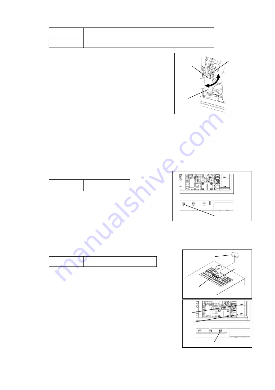
(4) Fuel Strainer Cleaning/Replacement


Cleaning


1st time: 50 hours


2nd time and after: Every 100 hours 

Replacement


Every 400 hours 


1)


Place a container under Fuel Filter to catch fuel spilling 

out of the filter.


2)

 Turn the fuel valve to "CLOSE". 


3)

 Turn the retainer ring counter clockwise and remove 

the cup and element. 

4)

 Remove any water or foreign material from the cup 

and clean the element using compressed air. 

Or replace the element.

) 

5)

 Install in the reverse order of removal. 


<Note> 

  Check that no foreign material is adhering to the packing then install the cup.


  After installation, turn the fuel valve to "OPEN" and check that there is no fuel leakage. 

After checking, turn the fuel valve to "CLOSE".


  Element part no.: 16271-43561 (Kubota part no.) 


   Always be sure to wipe away any spilled fuel.


  If water gather

s in the cup, drain water from the fuel tank. (Refer to section “10, 

Inspection/Maintenance (5) Draining Water from the Fuel Tank”)


(5) Draining Water from the Fuel Tank


Draining 
Water


Every 200 hours


1) 

Set a container to catch spilled water.


2) 

Remove the fuel drain plug and packing. 

3)

 Drain the water and tighten the fuel drain plug.


<Note> 

  Replace the packing with a new part each time you drain the water.


  Packing part no.: 6C090-58961 (Kubota part no.)


  Always be sure to check that there is no fuel leakage after tightening the fuel drain plug.


(6) Coolant Replacement


Change


Every 2,000 hours or 2 years 

Coolant Total Capacity: Approximately 4 L 
(Including the sub tank capacity of approx. 0.6 L)


1)

 Set a container to catch spilled coolant. 

2)

 Open the top plate. 

3) 

Remove the radiator cap. 

4)

 Remove the water drain plug and packing. 

5) 

After the coolant has been drained, reinsert the coolant drain 
plug with new packing. 

6)

 Remove the sub-tank and empty the coolant from the   

sub tank. 

7) 

Reattach the sub-tank to its original position and fill with 

coolant until it reaches the FULL level.


8)

 Fill the radiator with coolant until it reaches the filler neck. 

9)

 Re-attach and tighten the radiator cap.


10) 

Close the top plate.


Retainer   
Ring 

Element


Close 

Open 

Fuel 

Valve


Radiator Cap 

Water   
Inlet


Top Plate 

Fuel Drain Plug 

Water Drain Plug 

Full 

Low 

Summary of Contents for DG15BMK

Page 1: ...ertical Water Cooled 4 Cycle Diesel Engine DG15BMK UKV X753 008 72 0 X753801 590 0 CAUTION Do not operate the Generator or any other appliance before you have read and understood the instructions for...

Page 2: ......

Page 3: ...istributor which the generator was purchased if you have any inquiries regarding proper disposal The following conventions will be used throughout the manual to indicate the degree of caution Danger W...

Page 4: ...ulations if any for the education training in relation to the engine driven machine fuel handling qualification first aid etc The following statement refers to the noise level data contained in the EC...

Page 5: ...000 6 2 2005 the requirements of Directive 2011 65 EU use of harmonized standard EN IEC 63000 2018 the requirements of Directive 2000 14 EC Noise measurements have been made in accordance with 2000 14...

Page 6: ...ocedures 18 6 2 Installation Procedures 19 7 Load Connections 20 7 1 Load Cable Selection 20 7 2 Connecting Load Cables 21 8 Pre Operation Inspection 24 8 1 Checking Engine Oil 25 8 2 Checking Coolant...

Page 7: ...devices using AC output receptacles Do not operate the equipment with an incorrectly adjusted Earth Leakage relay to avoid electrical shock when the relay is not properly set Check on site regulation...

Page 8: ...Persons using a heart pacemaker are not allowed near the Generator work area while the Generator is in operation without the permission of a doctor The welder generates a magnetic field while energiz...

Page 9: ...ms such as a trailer and additional fuel tank added to the equipment Always be sure to use the top mounted lifting lug when lifting up the generator and raise it slowly at a completely vertical angle...

Page 10: ...Fire Part no X564 000640 Suffocation from exhaust fume Part no X564 000620 Lifting eye Part no X505 000240 Caution Hot surface Part no X505 006420 Caution Burns Part no X505 006410 Keep 1 meter Part...

Page 11: ...6 LABEL REPRODUCTION X564 000640 X564 000620 X505 000240 X505 006420 X505 006410...

Page 12: ...7 M707 000260 X564 000630 X564 000610 X505 004890 X505 006430 X564 000650...

Page 13: ...Tank Capacity 0 6 L included Starting Method Starter Motor CO2 Emission data Non road steady state test cycle g kWh 1047 4 Battery 46B24L Japanese Industrial Standard Fuel Tank Capacity L 37 Dimensio...

Page 14: ...e the equipment for any applications not listed above Improper usage can result in an accident or malfunction If using the equipment as a power source for medical equipment you must check with the med...

Page 15: ...PHASE Receptacle 415V 32A 3 PHASE ELR Relay Preheat Lamp Emergency Stop Switch 1 PHASE Receptacle 240V 16A 1 PHASE Receptacle 110V 16A 1 PHASE Receptacle 110V 32A 1 PHASE Breaker 240V 20A 1 PHASE Brea...

Page 16: ...er Lifting Lug Fuel Inlet Fuel Inlet Cover Positioning handle Not to be used for lifting Spill Containment Coolant Sub Tank Battery Oil Drain Plug Side Door Fuel Valve Fuel Strainer Fuel Drain Plug Oi...

Page 17: ...y drain the fluid from the spill containment because any rainwater induced into the equipment accumulates in the spill containment Although the fluids consist of oil fuel and coolant the spill contain...

Page 18: ...diately after stopping the equipment Hot coolant and steam will spurt out Always be sure to stop the engine and leave the engine to cool down before performing any inspection maintenance such as engin...

Page 19: ...0 1 Engine Oil Replacement The charge monitor cannot detect battery deterioration or insufficient battery fluid Inspect the battery fluid level periodically Refer to section 8 6 Checking the Battery I...

Page 20: ...tting off the circuit for protection against any accident such as electrical shock The sensitivity current of the earth leakage relay can be adjusted from 30mA to 1 000mA with duration of 0 04sec to 2...

Page 21: ...A ON OFF 1000mA ON OFF Selection of Operating Time not applicable to 30mA Time setting Slide switch position Switch 5 6 7 8 0 04sec or less ON OFF 0 3sec 0 2 0 36 sec ON OFF 0 5sec 0 4 0 6 sec ON OFF...

Page 22: ...ounding earth on to the terminal directly as shown right Securely ground the bonnet grounding terminal to the metal frame of the vehicle if transporting the equipment by truck or trailer 4 If an Earth...

Page 23: ...t Procedures Warning Injuries Do not lift up by positioning handle Doing so could cause the generator to fall No persons should ever be under a lifted generator Caution Injuries Always be sure to use...

Page 24: ...area such as indoor private home and or similar location or within a tunnel because the engine exhaust fume includes components that are harmful to humans Do not direct exhaust fumes at bystanders or...

Page 25: ...xcessively salty location can result in a clogged radiator or overheating resulting in malfunction fault or reduced insulation of electrical components 7 1 Load Cable Selection Caution Property Damage...

Page 26: ...the output terminal cover before operating Always be sure to stop the engine and remove the starter key before performing any equipment check or maintenance The person performing the maintenance must...

Page 27: ...ase load Terminal voltage is 415 V For single phase load Terminal voltage is 240 V For single phase load Terminal voltage is 415 V 2 Single Phase Output Terminal and Receptacle For single phase 110 V...

Page 28: ...up to the kVA as shown below 3 Phase 415V Output Terminal Receptacle Total 13kVA 13kVA 13kVA 1 phase 240V Output Terminal Receptacle Total R O S O T O 4 8kVA 4 8kVA 4 8kVA 10 4kVA 4 8kVA 3 6kVA 4 8kV...

Page 29: ...nspect or perform maintenance to the equipment near fire open flames or sparks Always locate a fire extinguisher near working space Caution Burns The engine muffler and similar parts and surrounding c...

Page 30: ...on and if it has decreased fill with oil until it reaches the maximum level Note The oil level cannot be accurately checked if the equipment is at an angle Operating the equipment when the oil has bee...

Page 31: ...annot be accessed by children Engine coolant could leak if the radiator is not completely tightened or there is a gap in the seating face Always be sure to securely tighten the radiator cap Do not add...

Page 32: ...ll Containment Warning Fire Spilled fuel and oil accumulates in the spill containment Do not operate the equipment with fluid accumulated in the spill containment Open the side door check inside of th...

Page 33: ...harge the battery Battery Replacement Procedures 1 Remove the battery negative cable Always be sure to remove the negative side first 2 Remove the battery hold down clamp 3 Remove the positive cable 4...

Page 34: ...r maintenance The person performing the maintenance must always keep the key Warning Electromagnetic Interference Persons using a heart pacemaker are not allowed near the generator without the permiss...

Page 35: ...Do not open any doors during operation Operating with a door open can negatively affect cooling effect resulting in an equipment malfunction Use ear protection if the level of noise is high Failure to...

Page 36: ...6 Wait for air to be completely bled from the fuel pipes and engine speed to stabilize approx 1 minute Engine speed is not stable until all air is bled from the fuel pipes Note Do not apply any loads...

Page 37: ...device turn the starter switch to STOP Do not strike the emergency stop switch with a hammer or similar tool Only use the emergency stop switch for emergency stop purposes If the engine does not stop...

Page 38: ...em 4 Spill Containment Fluid Level 1 Spill containment accumulated fluid has exceeded the specified level making it necessary to flush the fluid 5 Engine Overspend 2 Engine speed is exceeded 4140 min...

Page 39: ...nce The person performing the maintenance must always keep the key Do not touch the equipment during operation if the equipment or your body is wet Do not operate the equipment with any doors or cover...

Page 40: ...of a door or panel fixed by bolts when it is necessary to do so except the side door Please be careful about a strong wind and the opening and shutting of the door When a door is opened or closed sudd...

Page 41: ...ery 100 hours 1 Set a container to catch spilled engine oil 2 Remove the oil filler 3 Remove the oil drain plug and drain the engine oil 4 After the oil has been drained close and tighten the oil drai...

Page 42: ...pleted 3 Air Filter Element Cleaning Replacement Cleaning Every 100 hours Replacement Once in 6 times cleaning or 1 year 1 Remove the air cleaner clips and cleaner cap 2 Remove the element 3 Clean or...

Page 43: ...Draining Water Every 200 hours 1 Set a container to catch spilled water 2 Remove the fuel drain plug and packing 3 Drain the water and tighten the fuel drain plug Note Replace the packing with a new...

Page 44: ...eak if the drained fluid contains oily components If this occurs check for leakage locations Although the fluids that can leak internally consist of oil fuel coolant and battery fluid the spill contai...

Page 45: ...spill containment has a leak request repair at the retail outlet where the equipment was purchased Warning Electric Shock Injuries Always be sure to stop the engine and remove the starter key before p...

Page 46: ...ty and little dust with a cover or similar protection covering it Note Recharge a removed battery approximately once every month Warning Electric Shock Injuries Do not touch the equipment during opera...

Page 47: ...r oil filler during operation will result in hot oil spurting out Refer to the table below to perform inspection when the equipment is operating poorly If you cannot resolve a problem after inspecting...

Page 48: ...43 13 Engine Wiring Diagram...

Page 49: ...44 14 Generator Wiring Diagram...

Page 50: ......

Page 51: ......

Page 52: ...1 7 2 SUEHIROCHO OHME TOKYO 198 8760 JAPAN PHONE 81 428 32 6118 FAX 81 428 32 6145 2021 Printed in Japan...

Reviews: