Parameter Description
Parameters
125
Note: 1. The default value
are P.80=2(RL)
,
P.81=3(RM)
,
P.82=4(RH)
,
P.83=0(STF)
,
P.84=1(STR)
,
P.86=30(RES)
,
P.1
26=5(AU)
,
P.550=57(
HDI_FRQ
).
2. If the setting of P.80~P.84, P.86, P.126 and P.550 are changed, the functions of the terminals are
modified too. For example, when P.80 is equal to 2, the M0 terminal is used for RL. When P.80 is
changed to 8, than the M0 terminal function will be changed to RT, i.e., the second function
selection terminal. Take another example, if P.83 is equal to 0, the STF terminal will be STF
forward rotation function. When P.83 is changed to 6, then STF terminal function will be changed
OH, i.e., the external thermal relay terminal.
3. Wiring for the external thermal relay (OH): for the conventional motor wiring, the external thermal
relay is often placed at the front of the motor to prevent the motor from overheating. When the
external thermal relay is separated, the alarm of the inverter will be tripped off and “OHT” will be
displayed on the screen.
4. The operation of the inverter can be controlled by four means (“1” for terminal close, “0" for
terminal open, and X = 0, 1, 2, 3, 4, 6).
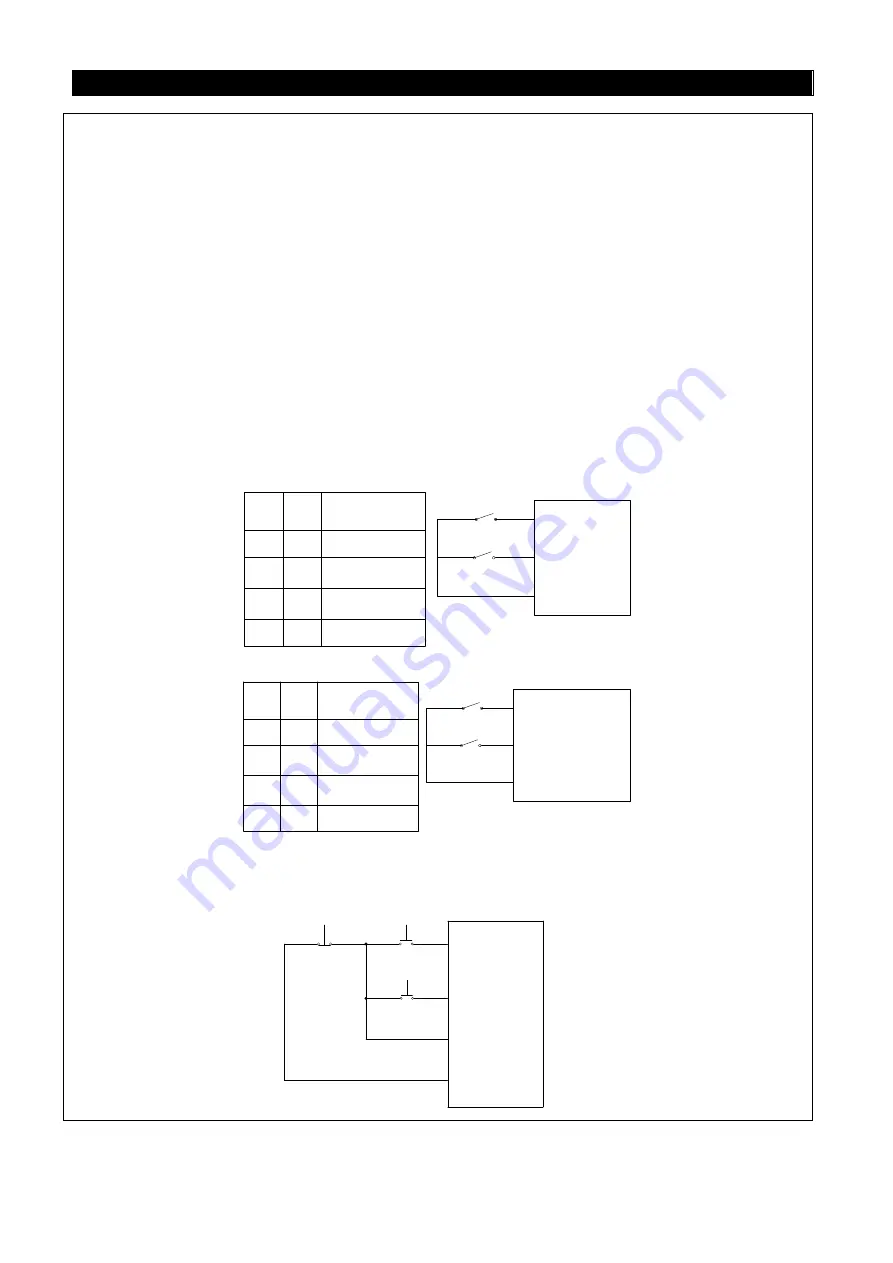
(1) Two-wire control mode 1:
K0
K1
STF(P.8X=0)
STR(P.8X=1)
SD
K0
K1
Operating
Instructions
0
1
0
1
1
1
0
0
Stop
Run Forward
Run Reverse
Stop
(2). Two-wire control mode 2:
K0
K1
RUN(P.8X=28)
STF/STR(P.8X=29)
SD
K0
K1
Operating
Instrnctions
0
1
0
1
1
1
0
0
Stop
Run Forward
Run Reverse
Stop
(3). Three-wire control mode 1 (with self-maintenance function): K0 is for the STOP function that
is normally close. When it is open, the inverter will stop. K1 and K2 is the forward and reverse
signals that are normally open. They indicate that pulse signal is active, i.e., jog is valid.
STOP(P.8X=31)
K0
K2
K1
STR(P.8X=1)
STF(P.8X=0)
SD


