Primary Operation
Primary operation
48
Step
Description
3
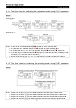
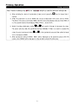
Turn on STF or STR to run the motor.
At this point, indicating lamp
or
will light up, indicating that the motor is
running.
Note: 1. For setting up the starting terminals STF and STR, please refer to P.78 and multi-function
terminal P.80~P.84
P.550 in Chapter 5.
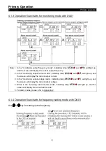
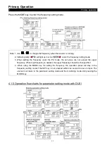
2. For detailed operation flow for the monitoring mode, please refer to Section 4.1.4.
3. If programmed operation mode is chosen, then STF and STR will become the starting
signal and the pause signal, respectively, instead of being the Run Forward or Run
Reverse terminals.
4
Turn off STF or STR to decelerate the motor until it comes to a full stop.
Indicating lamp
or
will not turn off until the inverter stops the output voltage.
4.2.3 Basic operation procedures for JOG mode (P.79=0 or 1)
Step
Description
1
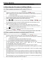
Change the operation mode to the JOG mode and indicating lamp
will light up. At this
point, the screen will display
before the motor starts to run.
Note: For selecting and switching the operation mode, please refer to Section 4.1.
2
Press
FWD
or
REV
to run the motor. At this point, indicating lamp
or
will light
up, indicating that the motor is running.
Release
FWD
or
REV
to decelerate the motor until it comes to a full stop.Indicating lamp
or
will not turn off until the inverter stops the output.
Note: 1. For detailed operation flow for the monitoring mode, please refer to Section 4.1.4.
2. In the JOG mode, the target frequency is the value of P.15, and the acceleration /
deceleration time is the value of P.16. Please refer to P.15 in Chapter 5.
4.2.4 Basic operation procedures for communication mode (P.79=0 or 2)
In the communication mode, the user can set the parameters and run/stop or reset the
inverters by communication. Please refer to P.33 for details.

