Parameter Description
Parameters
175
not available.
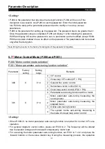
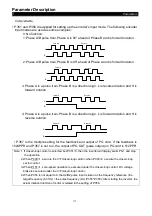
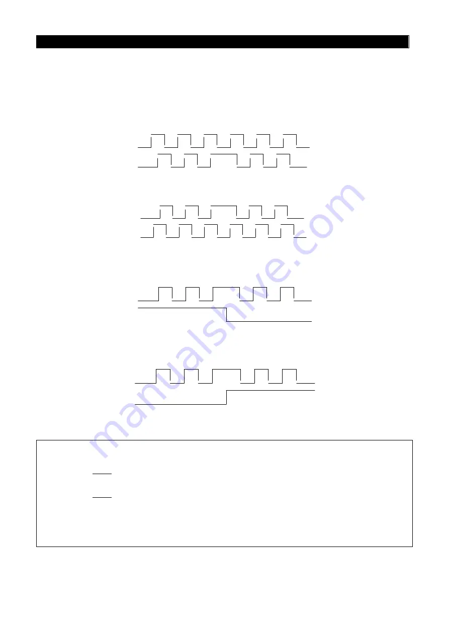
• P.351 and P.356 are applied for setting up the encoder’s input mode. The following encoder
input modes are used as some examples:
0: No function;
1: Phase A/B pulse train, Phase A is 90° ahead of Phase B and is forward rotation.
A
B
Reverse
Forward
2: Phase A/B pulse train, Phase B is 90° ahead of Phase A and is forward rotation.
A
B
Reverse
Forward
3. Phase A is a pulse train. Phase B is a direction sign. L is reverse rotation and H is
forward rotation
A
B
Reverse
Forward
4. Phase A is a pulse train. Phase B is a direction sign. L is forward rotation and H is
reverse rotation.
A
B
Reverse
Forward
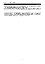
• P.357 is the multiple setting for the feedback and output of PG card. If the feedback is
1024PPR and P.357 is set to 2, the output of PG OUT (pulse output) on PG card is 512PPR.
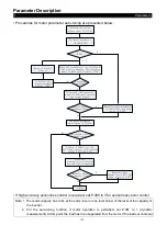
Note: 1. If closed-loop control is selected but P.351=0, then the inverter will display alarm PG1 and stop
the operation.
2. When P.300=1, execute the V/F closed-loop control; when P.300=4, execute the closed-loop
vector control.
3. When P.151=1, zero-speed operation is executed under the closed-loop control; DC voltage
brake is executed under the V/F closed-loop control.
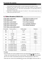
4. When P.356 is not equal to 0, the A2/B2 pulse input is taken as the frequency reference (the
target frequency (0.01Hz) =the pulse frequency (Hz) /P.355*P.359); After starting the inverter, the
actual rotation direction of motor is related to the setting of P.356.


