Shihlin Inverter Introduction
Inverter Introduction
26
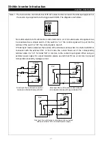
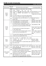
3.5.7 Toggle Switch Introduction
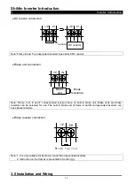
SOURCE
SINK
4-20mA
0-10V
0-20mA
0-10V
SW5
SW2
SW6
0-20mA
0-10V
SW4
HDI
PG
SW11 SW12
120
OPEN
SW10
4
AM2
AM1
NPN
HDI
R
AM1
HDO
AM1
Switch
number
Switch
state
Explanation
Remarks
SW2
*
Input 4~20mA current signal into terminal 4-5
Cooperating with P.17, please
refer to page 93.
Input 0~10V/0~5V voltage signal into terminal
4-5
SW4
*
Select the method of Sink Input
Please refer to note 1 in following
table.
Select the method of Source Input
SW5
*
Output 0~10V voltage from terminal AM2
Cooperating with P.538, please
refer to page 102.
Output 0~20mA/4~20mA current from terminal
AM2
SW6
*
Output 0~10V voltage from terminal AM1
Cooperating with P.64, please
refer to page 99.
Output 0~20mA/4~20mA current from terminal
AM1
SW10
Using 120
Ω
terminal resister
Set the terminal resister switch
on the farthest inverter at “120”,
please refer to page 72.
*
Without terminal resister
SW11
The terminal A2/B2 on PG03 is valid
Cooperating with
P.550
, P.356, P.522, please refer
to page 117, 166, 169
.
*
The terminal HDI is valid
SW12
The terminal HDO is valid
Cooperating with P.64, please
refer to page 99.
*
The terminal AM1 is valid
Note: The state with “*” is the default state of switch.


