Shihlin Inverter Introduction
Inverter Introduction
31
Terminal type
Terminal
name
Remarks and function description
Terminal specification
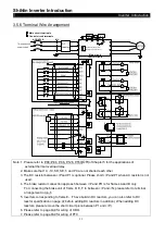
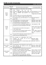
Pulse output
HDO
The output terminal of multi-function pulse. The external
frequency counter or analog meter can be connected to
it to indicate the output frequency, current, etc. The
function can be set by parameter P.54, P.74.
Minimum load:
4.7kΩ
Maximum current:
50mA
Maximum voltage:
48VDC
Communication
terminal
DA+ RS-485 communication interface, the function can be set
by parameter P.32
Highest rate: 19200bps
Longest distance: 500m
DB-
Common
terminal
SD
The common port of the terminals STF, STR, RES, M0,
M1, M2, M3, HDI, and HDO.(SINK)
---
SE
The common port of the open collector output terminals
SO1 and SO2.
---
5
The common port of the terminals 10, -10, 1, 2, 4, PTC,
AM1, AM2, DA+, and DB-.
---
PC
The common port of the terminals
STF, STR, RES, M0,
M1, M2, M3, and HDI.(SOURCE)
Output voltage:
24VDC±20%
Maximum current:
100mA
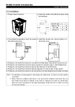
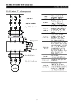
3.5.9 Wiring Precautions
Main circuit wiring:
1. Do not connect the power supply wires to the “motor connecting terminal
U/T1-V/T2-W/T3” or the inverter may be damaged.
2. Please do not mount phase advance capacitor, surge absorbers and electromagnetic
contactors at the output terminal of the inverter.
3. Please do not use “electromagnetic contactors” or “no-fuse switches” with an online power
to start or stop the motor.
4. Please ensure that the case of the inverter and of the motor are grounded to avoid
personnel electric shock.
5. To select appropriate diameter of the main wires and specification of the pressing
connection terminal, the no-fuse switch and the electromagnetic contactor, please refer to
Section 3.7. If the inverter is far away from the motor, please employ a wire with larger
diameter to ensure the voltage drop along the wire is within 2V. (The total length of the
wire shall not exceed 500 m)

