background image


1-17 


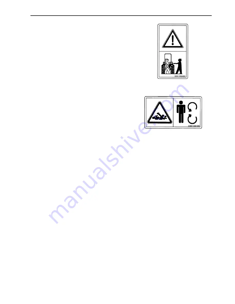
16. Location: Right hand side ROPS

.


WARNIMG: 

To avoid injury, do not stand on 

the implement or between the implement and 
tractor while operating the HPL lift or PTO 
controls. Always operate the HPL lift or PTO 
controls from operator seat. 

Part No. 390199460 


17. Location: PTO Guard

.


WARNIMG: 

To avoid injury, DO NOT clean, 

adjust, unclog, or service the PTO driven 
equipment when the tractor engine is running 
or all movement components have not 
completely stopped. Ensure that the PTO is 
switched off. 

Part No. 390199490 

Summary of Contents for ST460

Page 1: ...ST460 OPERATOR S MANUAL MODEL...

Page 2: ...on of your tractor Your SHIBAURA dealer carries a complete line of genuine SHIBAURA service parts These parts are manufactured and carefully inspected to insure high quality and accurate fitting of an...

Page 3: ...2 CONTENTS GENERAL INFORMATION AND SAFTY 1 1 CONTROLS INSTRUMENTS AND OPERATION 2 1 LUBRICATION AND MAINTENANCE 3 1 SPECIFICATIONS 4 1 INDEX 4 12 PRE DELIVERY SERVICE 4 15 PRE DELIVERY CHECKLIST 4 17...

Page 4: ...the back of this manual without charge except for lubricant oil or filters replaced as part of normal maintenance MAKE SURE THAT YOU AND THE DEALER SIGN BOTH COPIES A PRODUCT IDENTIFICATION PLATE is...

Page 5: ...non genuine parts and accessories Only genuine SHIBAURA replacement parts should be used The use of non genuine parts may invalidate legal approvals associated with this product It is prohibited to ca...

Page 6: ...51 4 53 9 69 6 42 7 54 2 57 9 73 5 M12 4T 1 75 27 5 34 7 37 3 47 1 1 25 31 8 40 5 43 1 54 9 7T 48 5 61 5 65 7 83 4 55 0 69 4 74 5 94 1 10T 68 0 85 4 92 2 116 73 1 93 3 99 0 127 M14 4T 2 0 46 3 59 3 6...

Page 7: ...cise every appropriate means to avoid a surprise involvement with machinery The word DANGER denotes a forbidden practice in connection with a serious hazard Failure to follow the CAUTION WARNING and D...

Page 8: ...eep all safety decals clean of dirt and grime and replace all missing illegible or damaged safety decals See the list of decals in the decal section of this manual 9 Install all guards before starting...

Page 9: ...gine is running Unexpected tractor movement can result from such contact 6 Before leaving the tractor park the tractor on level ground apply the parking brake lower the attached implements to the grou...

Page 10: ...r service the PTO driven equipment when the tractor engine is running or all movement components have not completely stopped Ensure that the PTO is switched off 5 Ensure the PTO master shield is insta...

Page 11: ...SHIBAURA Dealer If however service operations are to be undertaken on parts that contain asbestos the essential precautions listed below must be observed Work out of doors or in a well ventilated area...

Page 12: ...th It is advisable to have a fire extinguisher near or on the tractor when operating in conditions where a fire may occur Ensure fire extinguishers are serviced according to the manufacturers instruct...

Page 13: ...or cleaning purposes 12 Arrange fuel purchases so that winter grade fuels are not held over and used in the spring SAFETY FRAME ROPS Your SHIBAURA Tractor is equipped with a safety frame It must be ma...

Page 14: ...considerable spillage 2 In general avoid skin contact with all fuels oils acids solvents etc Most of them contain substances which may be harmful to your health 3 Modern oils contain additives Do not...

Page 15: ...ith you Please take this Manual and walk around your tractor noting the location of the decals and their significance Review the decals and operating instructions detailed in this Manual with the mach...

Page 16: ...nds and clothing away from rotating fan and drive belt Part No 390198020 3 Location On the radiator cap WARNIMG Pressurized cooling system Allow to cool then remove cap carefully Using a cloth turn ca...

Page 17: ...No 390199430 7 Location Starter Motor WARNIMG Do not start the engine by shorting across the starter terminals Tractor will start in gear if normal circuitry is bypassed NEVER start the engine while...

Page 18: ...Read the Operator s Manual before attempting to tow the tractor Part No 390199510 11 Location Front of Left hand side fender CAUTION Wear close fitting clothing and use all the Personal Protective Eq...

Page 19: ...seat belt when the tractor is equipped with a ROPS with raised locking position Part No 390199480 14 Location Left hand side ROPS WARNIMG To avoid serious injury always raise the ROPS and lock it when...

Page 20: ...ift or PTO controls Always operate the HPL lift or PTO controls from operator seat Part No 390199460 17 Location PTO Guard WARNIMG To avoid injury DO NOT clean adjust unclog or service the PTO driven...

Page 21: ...Operator s Platform PTO speed shift Lever PART NO 390171170 LOCATION Left Side Control Panel Position Control Lever PART NO 390372490 LOCATION In Side of Right Fender Range Selector Lever PART NO 3901...

Page 22: ...itch PART NO 390380791 LOCATION Left Side of Dash Road Light High Beam Switch PART NO 390230810 LOCATION Left Side of Dash Throttle PART NO 390430290 LOCATION Right Side of Dash Hazard Flasher Light S...

Page 23: ...T NO 390372471 LOCATION Top of Flow Control Knob Power Steering Fluid PART NO 390230230 LOCATION Top of P S Reservoir Engine Oil PART NO 390230220 LOCATION Engine Oil Filler Cap Rear Remote Control Op...

Page 24: ...L SYMBOLS As a guide to the operation of your tractor various universal symbols have been utilized on the instruments controls switches and fuse box The symbols are shown below with an indication of t...

Page 25: ...related The properties of the track or field surface and the driving speed will be the predominant parameters WARNING Machine vibrations cause discomfort to the operator and in some cases his health...

Page 26: ...To extend the length of the seat belt pull out on the male end until the correct length is obtained To latch the belt insert the male end into the belt latch located on the right side of the seat Ensu...

Page 27: ...ilt the wheel push forward the lever and move the steering wheel forward or backward to the desired position If the wheel is not held in position when the lever is raised the steering wheel will sprin...

Page 28: ...er of the ROPS rearward Install two lock pins to anchor the ROPS firmly once in position To rise the ROPS reverse the above procedure WARNING Do not operate the tractor with the ROPS folded as a stand...

Page 29: ...immediately and investigate the cause 3 Battery Charge Warning Light Illuminates when the key switch is in the ON or HEAT positions and goes out when the engine is started If this bulb becomes lit du...

Page 30: ...rn to zero when the engine is not running 10 Rear PTO Speed Determined by the position of the needle on the tachometer The tachometer is marked to indicate 540rpm PTO speed Your tractor is equipped wi...

Page 31: ...d PRE HEATING THE SYSTEM Your tractor has a diesel engine Before starting a cold engine the pre combustion chambers must be heated To pre heat the engine turn the key switch to the HEAT position and h...

Page 32: ...Operator in the seat Fully depress and release Inching pedal NOTE Always use safe practices when starting your tractor Turn the key to the extreme right Position the hand throttle forward so that it i...

Page 33: ...ructions found on the battery STOPPING THE ENGINE Pull the hand throttle fully rearward and turn the key switch to the OFF position to stop the engine After full load operation allow the engine to run...

Page 34: ...SECTION 2 OPERATION 2 9 LIGHTING Your tractor equipped with Headlights Side and Taillights Brake Lights Flasher Warning Lights Turn Signals 1 3 2...

Page 35: ...Road Lights Switch Rear Position OFF Mid Position Illumination of Instrument Panel and Taillights Front Position Illumination of Road lights Instrument Panel and Taillights Road Lights High Beam Swit...

Page 36: ...e activated with the key switch in any position For your protection use the flasher warning lights when traveling on public roads day or night Flasher Turn Lights Turn Signals The turn signal lights a...

Page 37: ...sh the rocker switch Horn can be activated with the key switch in any position ELECTRICAL SOCKET for Trailer A standard seven pin socket is provided mounted on the left side of the tractor at the rear...

Page 38: ...d to increase engine rpm to its maximum speed Upon release of the foot throttle the engine speed will return to the rpm at which the hand throttle has been set or idle if the hand throttle is not at a...

Page 39: ...ver attempt to make sharp turns by using the brakes Brake Pedal Lock The brake pedal lock is used to secure the brake pedals together Lock the pedals together as shown in the illustration whenever the...

Page 40: ...the lever completely upwards To disengage front wheel drive move the lever fully downward IMPORTANT Use front wheel drive when additional traction is required while operating on loose soil in wet slip...

Page 41: ...t lever and a range speed selector lever and creep shift lever The combinations of shuttle shift main shift range selector and creep shift lever selections to obtain the 24 forward and 24 reverse spee...

Page 42: ...perator in the seat Fully depress and release Inching pedal IMPORTANT If the operator leaves the seat with the key in the ON position or the tractor running the inching pedal has to be fully depressed...

Page 43: ...ar 3rd to 2nd to 1st sequence Skipping gears while down shifting can damage components due to over speed TRANSMISSION RANGE LEVER Low Medium High The range lever is located by the left hand fender It...

Page 44: ...all the hydraulic pressure to the transmission hydraulic clutch packs There is not a dry clutch located in the engine flywheel area to control transmission drive IMPORTANT If the operator leaves the s...

Page 45: ...en turning the tractor If the lock is engaged when turning a loss of steering control will result To operate the differential lock depress and hold the pedal down until the lock is positively engaged...

Page 46: ...switch and then rotate counter clockwise to back the OFF position The PTO control switch must be in the OFF position to activate the safety start system and allow the engine to start IMPORTANT If the...

Page 47: ...IMPORTANT Do not attempt to change PTO speed shift lever while the PTO is moving The PTO speed shift gear is non synchronized The PTO control switch must be off positioned or inching clutch pedal must...

Page 48: ...creasing the engine RPM with the manual throttle control 5 If the equipment is operating properly shift to the desired operating gear 6 Control the PTO speed using the throttle Never operate in an ove...

Page 49: ...weight of the implement should always be installed between the tractor and the implement hitch WARNING Pull only from the drawbar Always use the drawbar or the lower links in the lowered position when...

Page 50: ...sure hood prop rod is fully engaged in the latched position before servicing any components that are located under the hood 2 To close lift hood until prop rod is not holding weight of hood then pull...

Page 51: ...ment side of the top link A special double diameter pin for the top link installation is standard equipment with your tractor Use the smaller diameter end of the pin for category I implements and the...

Page 52: ...behind the seat and between the ROPS uprights The tool box also incorporates a hanger bracket to support the top link of the three point hitch when not attached to an implement DRINK HOLDER A drink h...

Page 53: ...When the hydraulic lift control lever is moved to a higher or lower setting in the quadrant the system repositions the equipment to a higher or lower position and maintains the selected position The h...

Page 54: ...ion of the upper link draft sensing system is described in the following paragraph Upper Link Compression Loads As the equipment is pulled through the soil the draft caused by changes in soil resistan...

Page 55: ...as described above OPERATING IN BOTH POSITION AND DRAFT CONTROL The position control may be used together with the draft control as follow 1 Set the position control lever at the maximum desire imple...

Page 56: ...be adjusted any time the link is disconnected for service to the hydraulic system or any time the relief valve operation is noticed while the lift arms are at the full raise position Adjustment Proce...

Page 57: ...ngine and set at 1000 1500 rpm 6 Move the draft feedback rod rearward until the relief valve stops operating Adjust the length of the rod to match the rod hole with the draft arm pin then shorten the...

Page 58: ...DROP RATE CONTROL VALVE The drop rate control valve provides an adjustment to regulate the flow of oil from the lift cylinder This allows the operator to slow or increase the rate of drop of the lower...

Page 59: ...turned with a blade screwdriver In the 1 o clock position hydraulic fluid is directed to the HPL valve and rear remotes optional When a valve for another attached implement is plumbed to the three por...

Page 60: ...quick couplers 1 Valve 2 Valve 3 Valve NOTE The lever automatically returns to neutral when the cylinder reaches the limit of its stroke in either direction of travel WARNING Before disconnecting cyl...

Page 61: ...applications of the tractor brakes when pulling heavy towed loads at road speeds Always sit in the driver s seat while starting or driving the tractor Any towed vehicle whose total weight exceeds that...

Page 62: ...stable AG 260 70R16 1442 mm Not Adjustable IMPORTANT Never attempt to widen the tread setting by reversing the front wheels on a front wheel drive system NOTE Torque front wheel bolts to 175 N m Rear...

Page 63: ...42 1877 E 1305 1640 1975 F 1403 1738 2073 G 1509 1844 2179 H 1607 1942 2277 A N A N A N A AG 14 9 28 B 958 1338 1718 C 1064 1444 1824 D 1162 1542 1922 E 1260 1640 2020 F 1358 1738 2118 G 1464 1844 224...

Page 64: ...actor less implement so that approximately one third of the tractor weight is on the front wheels For optimum traction tractors equipped with front wheel drive should be ballasted so that 40 45 of mac...

Page 65: ...of 2 weights per tractor 30 kg each 60 kg total Optional Front Weight Extension Bracket If additional front weights are needed for counterbal ancing a rear mounted implement an optional front weight...

Page 66: ...he valve stem when the valve stem is at its highest point at the top of the wheel TIRE PRESSURE Tire pressure must be considered when adding weights implements or attachments to the tractor or damage...

Page 67: ...SECTION 2 OPERATION 2 42...

Page 68: ...st the intervals for operating in adverse environmental and working conditions The intervals should be shortened for sandy dusty and extremely hot operating conditions CAUTION Observe these safety pre...

Page 69: ...l Level Final Reduction Gear Cases Oil Level Lubrication Fittings Steering Linkage 3 Point Linkage Brake Pedal Power Steering Cylinder Pedal Shaft Drive Cover Shaft Pivot Shaft Every 50 Hours 1 7 2 11...

Page 70: ...s as ambient temperatures change In winter use winter grade diesel fuel only Otherwise the fuel may jell and block the fuel system Fuel Usage Safety UNDER NO CIRCUMSTANCES should gasoline alcohol or g...

Page 71: ...located at the rear of the front food Before removing the cap wipe all dust and dirt from around the cap to prevent debris from falling into the tank during filling Use an approved container and check...

Page 72: ...cation Fittings NLG 1 GRADE 2 EP GREASE WITH LTIUM SOAP NOTE Use the following chart to determine which SAE Grade engine oil to use In areas where prolonged periods of extreme temperatures are encount...

Page 73: ...Oil NOTE Change the engine oil and filter after the first 50 hours of operation then every 100 hours thereafter If the tractor is operated for extended periods of time at maximum rated power and spee...

Page 74: ...ith a thin film of new oil Screw the filter into place until the gasket contacts its mating surface then turn the filter approximately three quarters of a turn BY HAND DO NOT over tighten 4 Add the pr...

Page 75: ...nging the Fuel Filter NOTE Change the diesel fuel filter after the first 50 hours of operation then following every 200 operating hours thereafter 1 Close the shutoff valve the handle should be pointi...

Page 76: ...alled The tractor has run out of fuel The lines leading to or from the filter have been disconnected The injection pump has been removed and reinstalled WARNING Fuel oil in the injection system is und...

Page 77: ...jector Lines Bleed the injector lines if The tractor has run out of fuel New injectors have been installed The injection pump has been removed for service repairs To bleed the injector lines 1 Loosen...

Page 78: ...accessed by opening the tractor hood The air cleaner assembly contains two elements an outer primary element and an inner safety element To remove the primary element release the clips on the end cap...

Page 79: ...the clean air side of the element pleats 3 After cleaning the element check the inner diameter seals for damage If damage is present replace the primary element 4 Reinstall the primary element by ins...

Page 80: ...f engine power or excessive black exhaust smoke NOTE Conduct a visual inspection of the inner safety element by placing a light inside the element Little or no light will shine through the element if...

Page 81: ...filler hole Do not fill above the dipstick full mark 3 Reinstall the filler plug and dipstick HYDRAULIC SYSTEM OIL FILTER NOTE Replace the hydraulic system oil filter after the first 50 hours of oper...

Page 82: ...oil With the oil at normal operating temperature drain the system by removing the transmission and rear axle drain plugs Reinstall the drain plugs after all of the oil has drained out Discard the use...

Page 83: ...le container beneath the power steering reservoir to catch the used oil With the oil at normal operating temperature drain the power steering reservoir by removing the drain plug that located at botto...

Page 84: ...to remove the cap while the system is hot Always cover the cap with a thick cloth and turn it slowly counter clockwise to the first stop Allow all pressure to escape before removing the cap completel...

Page 85: ...and remove the hose Allow all water to drain from the system through the drain valves 3 Close the drain valve and slowly refill the system with a 50 50 solution of ethylene glycol antifreeze and wate...

Page 86: ...ead of the engine Fan Belt NOTE Check the condition of the fan beIt after every 50 hours of operation Check fan belt tension after every 200 hours of operation A belt driven fan located at the front o...

Page 87: ...ect during transport the ROPS must be replaced to retain the best protection Following an accident check the ROPS the operator s seat for possible damage Before operating the machine replace all damag...

Page 88: ...ry charge check the indicator Hydrometer on this battery as following shows Blue Good condition the level and gravity of electrolyte are good Red Necessary to charge electrolyte is week White Add the...

Page 89: ...y occur Do not UNDER ANY CIRCUMSTANCES short the field terminal of the alternator to ground Do not disconnect the alternator output lead or battery cables while the alternator is operating Do not remo...

Page 90: ...oad Lights Tail lights ACC Power Relay 2 15A Horn Brake Lamp PTO Valve 3 20A Turn Signal Hazard Lights Brake Lamp 4 15A Work Lamp Engine Control 5 25A Road lights Illumination Lamp of Instrument Panel...

Page 91: ...ANT Be careful not to touch the bulb with bare fingers Oil from the fingers can shorten the life of the bulb Use a protective cloth or glove when installing the new bulb TAILLIGHT FLASHER WARNING LIGH...

Page 92: ...s 6 Remove the left and right underside retaining screw from dash panel 7 Tilt steering wheel rearward to ease tilting of dash panel 8 Tilt dash panel rearward to gain access to underside of instrumen...

Page 93: ...tality Make sure the rim is clean and free of rust Lubricate both tire beads and rim flanges with soap solution Do not use oil or grease Use a clip on tire chuck with a remote hose and gauge This allo...

Page 94: ...175 N m Rear Wheel Torque 175 N m Check wheel bolt torque daily until torque stabilizes RIM TO DISC BOLT TORQUE Tighten the rim to disc bolts to the specified torque anytime the wheel spacing is chan...

Page 95: ...ractor forward or backward until the marks are at wheel hub height on the rear of the wheel 3 Measure and record the distance between the marks at the rear of the wheels 4 The difference between the d...

Page 96: ...travel becomes excessive or the parking brake efficiency is reduced the parking brake should be adjusted as follows 1 Check and if necessary adjust the foot brakes as previously described 2 Release t...

Page 97: ...l Maximum clutch pedal SSS travel is set to 160 mm and maximum inching pedal EHSS travel is set to 135 mm To adjust the clutch pedal 1 Loosen jam nut 2 Remove cotter pin and remove rod from pedal brac...

Page 98: ...re dump valve spool travel 3 Full inching pedal travel equates to a dump valve spool travel of 2mm 0 25 4 If required adjust the cable by loosening the lock nut on the cable at the turnbuckle and rota...

Page 99: ...the dipstick filler plug 2 The oil is at the correct level when it reads between the full mark and the lower end of the dipstick If the oil level is low add SAE 80 hydraulic oil through the combined d...

Page 100: ...o axle housing when checking oil level Fill the axle with SAE 80 hydraulic oil until the oil level is between the full mark and the lower end of the dipstick Reinstall the dipstick filler plug NOTE Ap...

Page 101: ...er housing pivot points front side and rear side should be greased after every 50 hours of operation under normal conditions Under extremely dirty conditions lubrication should be carried out more fre...

Page 102: ...Remove the battery and clean it thoroughly Be sure that it is fully charged and that the electrolyte is at the proper level Store the battery in a cool dry place above freezing temperature and charge...

Page 103: ...SECTION 3 LUBRICATION AND MAINTENANCE 3 36...

Page 104: ...SECTION 3 LUBRICATION AND MAINTENANCE 3 37...

Page 105: ...3 49 0 62 8 10T 39 8 51 4 53 9 69 6 42 7 54 2 57 9 73 5 M12 4T 1 75 27 5 34 7 37 3 47 1 1 25 31 8 40 5 43 1 54 9 7T 48 5 61 5 65 7 83 4 55 0 69 4 74 5 94 1 10T 68 0 85 4 92 2 116 73 1 93 3 99 0 127 M1...

Page 106: ...sion Ratio 23 5 1 23 5 1 Firing Order 1 3 4 2 1 3 4 2 Low Idle Speed 1000 50 RPM 1000 50 RPM Maximum Speed High Idle 3000 50 RPM 3000 50 RPM Rated 2800 50 RPM 2800 50 RPM Valve Clearance Cold Intake 0...

Page 107: ...C 71 C Fully Open 82 C 82 C Radiator Cap 110 kPa 110 kPa Antifreeze Ethylene glycol Ethylene glycol ELECTRICAL SYSTEM Main system Protection 40A Slow Blow fuse 40A Slow Blow fuse Number of fuses for C...

Page 108: ...Brakes FWD 3150 mm 3150 mm Max Turn Angle FWD 56 56 Front to Rear Axle Ratio 1 5968 1 5968 POWER TAKE OFF PTO Type Independent PTO mode Transmission PTO mode Independent PTO mode Transmission PTO mod...

Page 109: ...15 6 47 5 19 6 11 19 3 8 08 8 48 6 79 8 00 20 4 10 33 10 88 8 71 10 27 21 H 1 12 42 13 08 10 48 12 34 22 2 16 82 17 71 14 19 16 71 23 3 22 02 23 18 18 57 21 88 24 4 28 26 31 87 23 83 28 08 R E V E R...

Page 110: ...6 53 6 87 5 51 6 49 19 3 8 55 9 00 7 21 8 49 20 4 10 97 11 55 9 25 10 90 21 H 1 13 19 13 88 11 12 13 10 22 2 17 86 18 80 15 06 17 74 23 3 23 38 24 61 19 72 23 23 24 4 30 00 31 58 25 31 29 81 R E V E R...

Page 111: ...tion Control Type Mechanical Mechanical Draft Control Type Top Link Sensing Top Link Sensing Drop Rate Control Standard Standard Lift Capacity 24 Behind kg 1570 kg 1570 kg TIRES FRONT Small AG 8 16 8...

Page 112: ...SECTION 4 SPECIFICATIONS 4 7...

Page 113: ...Down 1911 mm 1911 mm Large Ag Tires UP 2585 mm 2585 mm Large Ag Tires Down 1944 mm 1944 mm Turf Tires UP 2454 mm 2454 mm Turf Tires Down 1813 mm 1813 mm Metric Ag Tires 2548 mm 2548 mm Metric Ag Tire...

Page 114: ...SECTION 4 SPECIFICATIONS 4 9 3 5 4 4 7 1 2 6...

Page 115: ...e Setting Note AG 8 16 1335 mm Not Adjustable AG 9 5 16 1442 mm Not Adjustable TURF 27 x 10 5 15 1462 mm Not Adjustable AG 260 70R16 1442 mm Not Adjustable IMPORTANT Never attempt to widen the tread s...

Page 116: ...1542 1877 E 1305 1640 1975 F 1403 1738 2073 G 1509 1844 2179 H 1607 1942 2277 A N A N A N A AG 14 9 28 B 958 1338 1718 C 1064 1444 1824 D 1162 1542 1922 E 1260 1640 2020 F 1358 1738 2118 G 1464 1844 2...

Page 117: ...tion 1 1 3 1 General Maintenance 3 17 Hazards Related to Vibration Exposure 1 22 Headlamp 3 24 Hood Latch 2 25 Horn 2 12 HPL Drop Rate Control Valve 2 33 Hydraulic Lift Rocker 2 33 Hydraulic Manifold...

Page 118: ...2 13 Tire Pressure 2 41 Tires 3 26 To the owner 0 1 Tool Box 2 27 Top Link Main Spring Adjustment 2 32 Towing the Tractor 2 24 Tractor Hydraulics 2 28 Tractor Storage 3 35 Tractor Weighting 2 39 Tran...

Page 119: ...SECTION 4 SPECIFICATIONS 4 14...

Page 120: ...Bolt Torque 74 5 N m 108 N m 3 20 4 _____PTO Shield Installed 2 22 5 _____Safety Decals and Instruction Decals Installed 1 12 1 20 6 _____Neutral Start Switches Operation 2 7 7 _____Parking Brake Oper...

Page 121: ...SECTION 4 SPECIFICATIONS 4 16...

Page 122: ...Bolt Torque 74 5 N m 108 N m 3 20 4 _____PTO Shield Installed 2 22 5 _____Safety Decals and Instruction Decals Installed 1 12 1 20 6 _____Neutral Start Switches Operation 2 7 7 _____Parking Brake Oper...

Page 123: ...SECTION 4 SPECIFICATIONS 4 18...

Page 124: ...SECTION 4 SPECIFICATIONS 4 19 NOTES...

Page 125: ...SECTION 4 SPECIFICATIONS 4 20...

Page 126: ...Printed in Japan ST460 300813390 110301 001 R HEAD OFFICE BYGS Shinjuku Bldg 2 19 1 Shinjuku Shinjuku ku Tokyo 160 0022 Japan URL http www ihi shibaura com...

Reviews: