A
B
C
D
E
F
G
H
1
2
3
4
5
6
7
8
9
10
11
12
VL-E610S/VL-E610H
VL-E660S/VL-E96E
VL-E98E
VL-E610S/VL-E610H
VL-E660S/VL-E96E
VL-E98E
SC9
TL531
TL532
TL535
C213
R211
R212
C212
TL524
IC201
C214
TL204
TL203
IC252
C261
C260
C20
L11
C22
C19
C25
X11
IC12
R23
R24
C24
C23
L252
C21
R20
R19
C208
L251
L207
L202
R203
R204
C201
C203
TL201
TL12
L201
TL11
C206
R208
C209
R209
C211
C210
TL521
TL507
TL506
TL537
SC3
TL517
IC551
TL510
C554
TL509
C553
L12
L102
R15
R16
R13
C116
C117
C118
C18
IC102
R112
R18
Q11
R17
C111
C112
C113
C110
C108
C114
C115
R111
C106
TL102
IC101
C103
C104
C560
R589
R596
Q552
R595
R587
R588
C566
R583
C568
R593
IC552
R577
R592
R591
R594
C565
C559
R586
D551
R570
R598
C561
TL504
R597
R571
C563
IC553
R581
Z1A
C570
C569
R590
R574
R575
R578
R576
C564
C562
R569
R573
C102
C101
L101
• This especially corresponds to
å
only.
The number of units is as follows.
• E660U : From 21st unit to 5020th unit (5,000 units)
• E665U : From 7th unit to 5006th unit (5,000 units)
9-1
9-2
P4701
R1404
TL4716
TL2601
C456
P2601
TL2602
Q405
TL451
TL4718
R408
R433
C6403
R6405
P4702
R6406
C6404
TL4721 R6451
TL4703
TL4701
TL4705
TL4704
TL4702
R6407
TL4706
Q404
TL4707
C6405
R6409
R6410
TL404
SC4701
R5456
TL401
C5452
R5457
TL402
R5454
TL403
R5453
R447
FL5451
TL9714
TL9711
TL9713
SC4702
TL9712
TL814
TL813
TL812
TL811
TL815
TL816
TL817
TL818
TL820
TL821
TL822
TL823
SC804
TL824
TL825
TL826
TL827
TL828
TL829
TL806
TL805
C890
TL915
TL917
SC901
TL919TL717
TL802
C844
C843
TL803
P701
R1819
C801
C831
R817
R929
C823
TL801
R815
R810
R809
R1818
R803
Q801
R800
R1817R1815
R816
R827
R814
R811
R812
R813
C803
R805
R802
R801
Q800
TL807
TL808
C845
R1816
TL819
R888
Q802
C851
C861
C854
C830
IC802
C866
R865
R883
R894
R892
TL804
R871
R870
R868
R867
R889
C849
TH800
IC801
R869
R873
R872
C847
R1814
TL810
TL809
TL830
TL4708
TL4714
C4412
C4413
TL4713
TL4712
R4414
R4415
TL4709
R4417
Q4405
R4416
C4453
C4454
TL4710
R4410
R4412
FL5401
R4409
Q4404
R5402
R5403
R5416
R5451
R5404
R5417
R5407
Q5401
C5402
R5405
Q5405
D5401
R5409
R5408
R5406
R5452
C5401
TH5401
C5403
R5410
R5412
Q5402
Q5404
Q5451
R5415
Q5403
R5413
C5405
C5404
R5455
R5458
C5406
R5414
R5411
Q6403
Q6401
L401
R6408
R6401
C449
FL6401
R6404
C6401
R6402
Q6402
X401
R6403
L6401
C6402
C453
C450
L404
R441
R444
C458
TL610
C8413
R8425
L8407
R8424
R8417
Q8407
Q8410
C8412
R8423
R8419
C8414
L8408
Q8405
R8420
R8418
R8422
C8411
R8428
C8408
L8405
C8415
R8429
Q8406
R7419
C8416
Q7406
R7418
TL7402
TL3319
Q7404
R8430
R7416
R7417
Q8408
Q8409
C7451
Q7451
R7453
R8401
Q8401
R8432
R8431
R7452
R7451
C714
R712
TL707
R724
R730
Q703
R723
R722
R2731
R2775
C703
R713
Q710
R2776
R2774
R2773
Q709
Q711
R2778
R2743
R2744
R2777
TL2701
Q712
R2747
TL9800
R2739
D705
R707 TL9708
TL9709
Q907
TL907
TL920
R905
R906
R904
TL942
Q904
Q909
R950
R908
TL906
Q903
Q908
IC902
R903
R1957
TL937
R1906
R1956
R1950
R1952
R907
C1919
R1912
R1951
R1918
Q911
C1917
R1926
R1923
R1943
R1922
R1925
R1944
R1945
Q933
R1928
R1942
Q929
R927
TL932
C1915
C940
R928
C941
TL925
TL913
TL945
TL914
CP901
TL944
TL911
TL943
SC902
SC903
TL902
TL908
TL901
TL904
TL918
TL9716
TL926
TL909
TL912
TL903
TL910
R940
CP902
L926
L932
TL947
C943
C930
R930
C1909
R1927
R1920
L923
R1919
R1914
R1913
R1908
R1907
C909
Q910
TL905
R910
L908
C907
L910
TL946
TL940
C910
L907
C939
L909
Q906
C908
L930
TL941
TL9704
R2746
R731
TL9705
Q713
R705
R2741
R714
R708
C705
C717
R703
C716
R757
R756
R2745
R2734
TL9703
X701
C718
TL3719
TL3704
TL3723
TL3707
TL3722
R2742
TL936
C3725
TL3705
TL3718
R3714
TL3706
IC3702
C701
TL3720
TL3721
TL3717
TL3713
C3724
R3707
TL3715
TL3714
C3721
TL3301
C3719
C3720
TL3716
TL3302
TL3303
TL3320
TL3321
TL3304
R3711
TL3309
TL3318
Q3701
R3709
TL3305
TL8401
TL3316
R3710
TL3307
TL405
TL7401
TL3317
TL608
TL3311
R3713
R3712
R8427
TL3312
TL3306
TL3315
TL3724
TL3313
R8426
TL3308
TL3725
TL3310
TL3314
TL609
Z2
TL607
SC601
C638
TL611
R602
R605
C609
C605
R603
C606
R606
R604
R628
R607
C610
C613
C614
R629
C626
C628
C621
TL602
TL603
TL604
TL601
C3718
R2737
R744
TL3726
C704
R755
R754
R753TL3727
C706
C3717
TL708
R771
R716
TL9707
TL702
R715
TL705
TL704
R770
R709
R738
R710
R737
R706
R701
R759
R761
R758
R702
TL9706
IC703
R704
TL706
R740
TL716
C719
C720
C721
C722
R745
TL701
R772
R773
C937
L929
C929
Q927
C928
C927
Q926
C944
C925
L931
Q928
L917
C921
C919
D906
L9801
C931
TL1925
TL8807
TL8808
TL8806
TL8809
TL9715
TL1928
TL9717
R2779
TL931
TL1926
TL1927
TL927
TL1929
R8820
C8826
TL8823
TL8820
TL8821
TL8818
TL8816
TL8815
TL8822
TL8824
TL8817
TL8812
SC904
C914
C920
Q913
L916
L915
L903
C916
D904
C918
C904
Q912
L922
C924
L921
C926
Q925
D901
C906
R8842
C8831
R732
R733
R763
TL713
C729
C8816
C702
TL709
C8817
R711
R765
R8806
R8807
R2738
R8809
C8823
R8808
C728
R2730
R8810
TL938
R764
R1733
TL703
R2750
R739
R736
R735
R741
R2740
D704
R734
R752
R750
R751
R742
R743
R2736
R746
R619
TL719
TL612
TL933
IC601
TL605
R608
R624
C607
R611
R601
R612
TL606
TL613
P601
TL712
R1721
Q714
C732
C731
L703
TL711
R777
TL710
C1710
IC1701
C1707
C1708
C1709
C1705
C1704
C1702
C1703
TL718
C1701
C715
C712
Q704
R727
R2781
L702
Q701
C708
R719
C709
Q702
D701
TL715
R776
R780
Q715
D702
IC701
TL714
R775
R718
C8821
R8815
D8800
R8812
R8836
C8819
Q8801
C8822
R8813
C8820
L8802
R8814
C8812
R8833
IC8801
IC8802
R8823
R8824
TL8803
C8827
TL8800
R8840
R8825
L8803
C8810
C8828
R8804
C8811
TL8826
C8804
R8841
C8808
C8805
L8801
TL8805
TL8825
C8800
R8839
IC9800
Q8803
R8819
R8817
C9800
C8825
Q8802
R8838
Q8800
R8837
TL8827
R8818
R8816
L9800
R9804
L911
Q905
L901
C911
C902
L904
C903
Q901
L914
TL8811
TL8813
R8822
TL8819
TL8814
TL8810
C8835
L1701
R1702
R1701
C1706
R1703
R1704
C1711
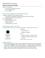
CAMERA P.W.B.
9. PRINTED WIRING BOARD ASSEMBLIES
9-1. P.W.B. Component Side SIDE A
MAIN P.W.B.