background image

UX-4000MU

FO-2950MU/C

No. 00ZUX4000USME

Parts marked with "

" is important for maintaining the safety of the set. Be sure to replace these parts with specified ones for maintain-

ing the safety and performance of the set.

This document has been published to be used
for after sales service only.
The contents are subject to change without notice.

SHARP CORPORATION

SERVICE MANUAL

Laser Wave Length  : 780 

±

15 nm

Laser Pulse Times   


: (13.95 

±

 3 

µ

s)/7mm

Laser Output Power : 0.4 mW 

±

 0.05mW

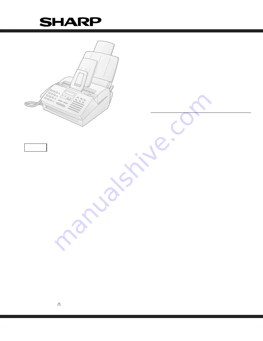
Illustration: UX-4000M

 CAUTION

This laser facsimile is a class 1 laser product that complies with 21CFR 1040.10 and 1040.11 of the CDRH or IEC60825-1 standard.
This means that this machine does not produce a hazardous laser radiation. The use of controls, adjustments or performance of
procedures other than those specified herein may result in hazardous radiation exposure.

This laser radiation is not a danger to the skin, but when an exact focusing of the laser beam is achieved on the eyes retina, there is
danger of spot damage to the retina.

The following cautions must be observed to avoid exposure of the laser beam to your eyes at the time of servicing.

1) When a problem in the laser optical unit has occurred, the whole optical unit must be exchanged as a unit, not an individual part.

2) Do not look into the machine with the main switch turned on after removing the toner/developer unit and drum cartridge.

3) Do not look into the laser beam exposure slit of the laser optical unit with the connector connected when removing and installing

the optical system.

4) The cover of Laser Printer Unit contains the safety interlock switch.

Do not defeat the safety interlock by inserting wedges or other items into the switch slot.

FACSIMILE

UX-4000M


MODEL

 FO-2950M

Summary of Contents for FO-2950M - B/W Laser - All-in-One

Page 1: ...other than those specified herein may result in hazardous radiation exposure This laser radiation is not a danger to the skin but when an exact focusing of the laser beam is achieved on the eyes retina there is danger of spot damage to the retina The following cautions must be observed to avoid exposure of the laser beam to your eyes at the time of servicing 1 When a problem in the laser optical u...

Page 2: ... 4 1 2 Wiring diagram 4 2 3 Point to point diagram and connector signal name 4 3 CHAPTER 5 CIRCUIT DESCRIPTION 1 Circuit description 5 1 2 Circuit description of control PWB 5 2 3 Circuit description of TEL LIU and Hook SW PWB 5 21 4 Circuit description of power supply PWB 5 23 5 Circuit description of CIS UNIT 5 24 CHAPTER 6 CIRCUIT SCHEMATICS AND PARTS LAYOUT 1 Control PWB circuit 6 1 2 TEL LIU ...

Page 3: ...grayscale 64 levels PC scan 256 levels Paper tray capacity 200 sheets 20 lb letter paper Compression scheme MMR MR MH Applicable telephone line Public switched telephone network Compatibility ITU T CCITT G3 mode Printing resolution Horizontal 406 lines inch 16 lines mm Vertical 391 lines inch 15 4 lines mm PC Printing 600 dpi enhanced 1 800 dpi Input document size Automatic feeding Width 5 8 to 8 ...

Page 4: ...0 PAPER CHECK TONER EMPTY PC IN USE LINE IN USE REDUCTION ENLARGEMENT COPY HELP START STOP TEL FAX A M FUNCTION VOLUME DOWN UP RECEPTION MODE RESOLUTION BROADCAST 01 02 03 04 08 07 06 05 12 11 10 09 16 POLL 15 14 13 20 G4 19 G3 18 G2 17 G1 1 2 3 4 7 8 9 13 14 15 16 20 19 21 17 18 22 10 11 12 5 6 13 14 15 16 17 18 19 20 21 22 BROADCAST key Press this key to send a document to a group of receiving f...

Page 5: ...ws Normal size max 20 sheets Special size single sheet only manual feed NOTES If you need to send or copy more 20 pages place the ad ditional pages and carefully in the feeder just before the last page is scanned Do not try to force them in as this may cause double feeding or jamming If your document consists of several large or thick pages which must be loaded one at a time insert each page into ...

Page 6: ...ve one installed contact the telephone company If the machine is moved from a cold to a warm place If the machine is moved from a cold to a warm place it is possible that the reading glass may fog up preventing proper scanning of documents for transmission To remove the fog turn on the power and wait approxi mately 2 hours before using the machine The laser printer in your fax machine uses a toner...

Page 7: ...ollowing keys Note This setting is only necessary after you have replaced the drum cartidge not after replacing the toner cartridge 9 FUNCTION CLR TONER COUNT PRESS START KEY START START Display shows 9 FUNCTION CLR DRUM COUNT PRESS START KEY Display shows 3 Replacing the drum cartridge To maintain excellent printing quality we recommend that you replace the drum cartridge after 20 000 pages have ...

Page 8: ...rt the drum cartridge into the print compartment aligning the guides on the cartridge with the runners on the sides of the com partment 6 Gently pull the paper tab to remove the black sheet of protective paper from the drum cartridge Be careful not the tear the paper or leave any pieces of paper in the machine 7 Replace the toner cartridge and reset the drum counter Refer to Installing the Toner C...

Page 9: ...lse dial line you must set your fax for pulse dialing Press the keys on the operation panel as follows 1 Press these keys The display will show DIAL MODE 1 TONE 2 PULSE 4 FUNCTION The machine does not have a power on off switch so the power is turned on and off by simply plugging in or unplugging the power cord Be sure to insert the line into the TEL LINE jack Do not insert it into the TEL SET jac...

Page 10: ...higher than the marked line Loading too much paper may cause paper jams and misfeeds If paper remains in the tray take it out and combine it into a single stack with the new paper before adding the new paper Important Be sure to load the paper so that printing takes place on the print side of the paper Printing on the reverse side may result in poor print quality 5 Make sure the stack of paper is ...

Page 11: ...ENT JAMMED appears in the display first try pressing the START key If the document doesn t feed out open the operation panel and remove it Important Do not try to remove a document without opening the operation panel This may damage the feeder mechanishm 3 Close the operation panel making sure it clicks into place 7 Clearing jammed printing paper 1 If most of the jammed page is protruding from the...

Page 12: ...m in the drum cartridge This will damage the drum surface Do not expose the drum to direct light This will damage the drum 7 Gently pull the jammed paper out of the machine If needed turn the wheel on the right side of the fusing unit to eject the paper from the machine Caution Do not use excessive force to pull the jammed paper out If the paper tears and a piece remains inside the machine a servi...

Page 13: ...ll up to open the cover Caution The fusing unit inside the print compartment becomes very hot during operation Do not touch the inside of the compartment or the paper guide on the underside of the print compartment cover Document rollers White backplate Scanning glass 2 Grasp the finger hold on the toner cartridge handle where it is marked PUSH and pull the handle out Rehold the handle and pull th...

Page 14: ... you must reset it This can be done as follows 1 Grasp the print compartment cover at both sides as shown and pull up to open the cover Caution The fusing unit inside the print compartment becomes very hot during operation Do not touch the inside of the compartment or the paper guide on the underside of the print compartment cover 2Use a ballpoint pen to press the RESET button Note Pressing the RE...

Page 15: ...ory is full This may occur during fax reception if too much data is received before the pages can be p r i n t e d o u t I f f a x e s h a v e b e e n received to memory because printing is not possible an additional mes sage will indicate the problem resolve the problem so that printing can continue MEMORY PRINTING The fax is preparing to or printing out a document from memory NO DATA This appear...

Page 16: ...the letter entry table in Entering Your Name and Num ber 7 Press OWN NUMBER SET PRESS START KEY A B C D E F G H I J K L M N O P Q R S T U V W X Y Z SPACE To change case press the REDIAL key Press or to scroll through symbols and special characters 6 When finished press FAX TEL MODE 1 SET 2 CLEAR DATE TIME SET PRESS START KEY START START START START START START START STOP FUNCTION FUNCTION STOP STO...

Page 17: ...upply PWB 2 High voltage power adjustments The high voltage power adjustments are composed of the MC output voltage adjustment and the DC bias output voltage adjustment Either adjustment is performed with the diag function MAIN CHG ADJUST MODE 1MC output voltage adjustment In the measurement circuit shown below adjust VR1 to be 1050V 1200V aim at 1100V MC Measure with the high voltage tester effec...

Page 18: ...e check DRUM DC Bias 3Transfer charger voltage check After MC output voltage adjustment and DC bias output voltage ad justment check transfer charger voltage Check that the output voltage is 3200V 3700V For measurement use a high voltage tester effective value meter Transfer charger Output voltage check DRUM D7 D8 Note For measurement do not remove Printer PWB from the bottom plate VR1 MC output v...

Page 19: ...ION SETTING PRESS or KEY DIAL MODE 1 TONE 2 PULSE KEY KEY DISPLAY step 4 End using the STOP key step 3 Select using 1 or 2 step 2 Select DIAL MODE Push until DIAL MODE is indicated because the number of s changes by the models 1 2 PULSE SELECTED STOP 1 F100 ICPS10 is installed in order to protect IC s from and overcurrent generated in the verification stamp drive circuit If F100 is open replace it...

Page 20: ...T MODE START 02 CHECK PATTERN 1 START 03 CHECK PATTERN 2 START 04 CHECK PATTERN 3 START 05 PAPER FEED AGING START 06 LIFE SET MODE START 07 LIFE ALL CLEAR START START 08 LIFE ENTRY MODE START 09 TOP ADJUST MODE START START Then press the key Select the desired item with the key and the key or select with the rapid key Enter the mode with the key START 10 LIFE CLEAR MODE START 11 MAIN CHARGER ADJUS...

Page 21: ...e turned on or off while using image memory S O F T S W I T C H M O D E S W 0 1 0 0 0 0 0 0 0 0 Soft switch mode screen Switch No 1 2 3 4 5 6 7 DATA No 8 Data S O F T S W I T C H M O D E S W 0 2 0 0 1 0 0 0 0 0 S O F T S W I T C H M O D E S W 1 S O F T S W I T C H M O D E S W 1 5 0 0 1 0 0 0 0 0 1 6 The buzzer beep pattern is on for 0 25 seconds and then off for 0 25 seconds 3 Aging mode If any do...

Page 22: ... will be continuously set as they are 12th and subsequential letters of the destination name registered in the Rapid number 01 will be discarded 2 2 Print diagnosis Rapid key 01 Area print mode The effective printing area frame is printed in the specified sheet size The left pattern is repeated The left pattern is repeated The left pattern is repeated 5 Longitudinal strip 2 pattern Black 2 dot and...

Page 23: ...T N E R 0 0 1 2 3 0 L F Rapid key 07 Life all clear The mode is used to clear the life counter of the printer of the counter of the auto feeder Note The counter shows the operational state of the printer e g how many sheets have been printed since start of use The ordi nary memory does not reset the counter Accordingly it is nec essary to reset this counter in addition to the ordinary memory clear...

Page 24: ...the or key if desired Press the STOP key to exit from the mode Note The counter shows the operational state of the printer how many sheets have been printed since start of use and others The ordinary memory does not reset the counter Accordingly it is necessary to reset the counter or do the clear process in addi tion to the ordinary memory clear if the content in the memory on the control PWB is ...

Page 25: ...0 0 0 0 0 0 0 S F T S W 1 1 0 0 0 0 0 0 0 S F T S W 1 1 0 0 0 0 0 0 0 S F T S W 1 1 0 0 0 0 0 0 0 S F T S W 2 0 0 0 0 0 0 0 0 S F T S W 53 0 0 0 0 0 0 0 0 Press key during setting To finish the settings halfway between SW 1 and SW53 press the STOP key In this case the setting being done to the SW No on display will be nullified while settings done to the preceding SW Nos remain in effect The soft ...

Page 26: ... 5 6 7 8 0 7 0 OFF 0 0 0 0 off 0 8 0 Communication results printout Error Err Tmr Mem Send only No print Always OPTION 1 transaction report No 1 0 0 0 1 1 0 2 No 2 0 0 1 0 1 0 3 No 3 1 0 0 0 0 1 4 Delay timer before line connect in auto dial 3 sec 0 sec 0 SW4 Delay timer of after line connect in auto dial 3 6 sec 3 0 sec 1 7 sec 3 0 sec 5 No 5 1 1 0 0 0 6 No 6 1 0 1 0 1 Number of CNG detect STAND ...

Page 27: ...ception No 1 0 0 1 1 0 2 No 2 0 1 0 1 1 3 Dial pausing sec pause 2sec 4sec 1 SW8 4 Signal transmission level Binary input 16 8 4 2 1 0 5 No 4 5 6 7 8 1 6 0 1 0 0 0 8 dBm 0 7 0 8 0 CED tone signal interval 75ms 500ms 750ms 1000ms 1 No 1 0 0 1 1 0 2 No 2 0 1 0 1 0 3 Equalizer freeze control MODEM On Off 0 SW9 4 Equalizer freeze conditions All 7200bps 0 5 CED detection time 500ms 1000ms 0 6 Reserved ...

Page 28: ...ansmission level Low Binary input 16 8 4 2 1 0 2 No 1 2 3 4 5 1 3 0 1 0 0 0 4 0dBm 0 4 0 SW12 5 0 6 Reserved 0 7 Reserved 0 8 Reserved 0 1 DTMF signal transmission level High Binary input 16 8 4 2 1 0 2 No 1 2 3 4 5 0 3 0 0 1 0 0 2 0dBm 1 4 0 SW13 5 0 6 Reserved 0 7 Reserved 0 8 Reserved 0 1 Reserved 0 2 Reserved 0 3 Reserved 0 SW14 4 Reserved 1 5 Reserved 1 6 Reserved 0 7 Reserved 0 8 Reserved 0 ...

Page 29: ...s 1 FUNC 3 SW18 4 Sender s phone number setting Cannot change Change allowed 0 5 Polling key Yes No 0 OPTION 6 Activity report print Automatic printout No printout when memory full 0 OPTION 7 Total communication hours and pages print Off On 0 8 Line density selection Fine Standard 0 OPTION Density adjustment when Fine STD mode Normal Faint Deep Deep when Dark mode 1 No 1 0 0 1 1 0 2 No 2 0 1 0 1 0...

Page 30: ...ION 6 tel 0 9 No 5 6 7 8 Data No 1 7 EX 0 1 0 1 0 8 eg 5 1 1 Busy tone detection ON OFF time Shorter duration 350ms 150ms 0 Busy tone detection ON OFF time 650ms 900ms 2700ms 900ms 2 Longer duration No 2 0 0 1 1 0 3 No 3 0 1 0 1 1 SW25 4 Busy tone continuous sound detect time 10sec 5sec 1 5 Busy tone detect continuation sound detect No Yes 0 6 Busy tone detect intermittent sound detect No Yes 0 Bu...

Page 31: ...ed 0 5 Reserved 0 6 Reserved 0 7 Reserved 0 8 Reserved 0 1 Reserved 0 2 Reserved 0 3 Reserved 0 SW29 4 Reserved 0 5 Reserved 0 6 Reserved 0 7 Reserved 0 8 Reserved 0 1 Reserved 0 2 Reserved 0 3 Reserved 0 SW30 4 Reserved 0 5 Reserved 0 6 Reserved 0 7 Reserved 0 8 Reserved 0 1 Reserved 0 2 Reserved 0 3 Reserved 0 SW31 4 Reserved 0 5 Reserved 0 6 Reserved 0 7 Reserved 0 8 Reserved 0 SW NO DATA NO IT...

Page 32: ...rved 1 1 Reserved 1 2 Reserved 1 3 Reserved 0 SW35 4 Reserved 1 5 Reserved 1 6 Reserved 1 7 Reserved 0 8 Reserved 1 1 Reserved 1 2 Reserved 1 3 Reserved 1 SW36 4 Reserved 1 5 Reserved 1 6 Reserved 1 7 Reserved 0 8 Reserved 0 1 Reserved 0 2 Reserved 0 3 Reserved 0 SW37 4 Reserved 0 5 Reserved 0 6 Reserved 0 7 Reserved 0 8 Reserved 0 1 Reserved 0 2 Reserved 0 3 Reserved 0 SW38 4 Reserved 0 5 Reserve...

Page 33: ...rved 0 SW41 4 Reserved 0 5 Reserved 0 6 Reserved 0 7 Reserved 0 8 Reserved 0 1 Reserved 0 2 Reserved 0 3 Reserved 0 SW42 4 Reserved 0 5 Reserved 0 6 Reserved 0 7 Reserved 0 8 Reserved 0 1 Reserved 0 2 Reserved 0 3 Reserved 0 SW43 4 Reserved 0 5 Reserved 0 6 Reserved 0 7 Reserved 0 8 Reserved 0 1 Reserved 0 2 Reserved 0 3 Reserved 0 SW44 4 Reserved 0 5 Reserved 0 6 Reserved 0 7 Reserved 0 8 Reserve...

Page 34: ...served 0 5 Reserved 0 6 Reserved 0 7 Reserved 0 8 Reserved 0 1 Reserved 0 2 Reserved 0 3 Reserved 0 SW48 4 Reserved 0 5 Reserved 0 6 Reserved 0 7 Reserved 0 8 Reserved 0 1 Reserved 1 2 Reserved 0 3 Reserved 0 SW49 4 Reserved 0 5 Reserved 0 6 Reserved 0 7 Reserved 0 8 Reserved 0 1 Reserved 0 2 Reserved 0 3 Reserved 0 SW50 4 Reserved 0 5 Reserved 0 6 Reserved 0 7 Reserved 0 8 Reserved 0 SW NO DATA N...

Page 35: ...eserved 0 8 Reserved 0 1 Reserved 0 2 Reserved 0 3 Reserved 0 SW52 4 Reserved 1 5 Reserved 1 6 Reserved 0 7 Reserved 1 8 Reserved 0 1 Reserved 0 2 Reserved 0 3 Reserved 1 SW53 4 Reserved 0 5 Reserved 0 6 Reserved 0 7 Reserved 1 8 Reserved 1 SW NO DATA NO ITEM Switch setting and function Remarks Initial setting 1 0 ...

Page 36: ... connection and dial data output under the auto dial mode SW4 No 7 No 8 Number of CNG detect STAND BY mode Used for detection of CNG in 1 to 4 pulses SW5 No 1 Time format When this switch is set to 0 time is displayed in 12 hour system When set to 1 24 hour system SW2 No 4 CNG detection in standby mode The CNG signal detection function during stand by stops 0 Yes 1 No SW2 No 5 Polling security Thi...

Page 37: ...er for V 29 transmission mode Though transmission of a non modulated carrier is not required for trans mission by the V29 modem according to the CCITT Recommendation it may be permitted to send a non modulated carrier before the image signal to avoid an echo suppression problem It may be useful for overseas communication to avoid an echo sup pression problem if set to 1 SW7 No 5 EOL detect timer 2...

Page 38: ...ssion by pressing the Start key in the key pad dialing mode When set to 1 CNG transmis sion in the key pad dialing mode cannot be performed In either case CNG transmission can be performed in the auto dial mode SW11 No 5 Error criterion Used to select error criterion for sending back RTN when receiving im age data SW11 No 6 Pulse to tone change by When setting to 1 the mode is changed by pressing ...

Page 39: ... the Resolution key is manually set to another mode SW19 No 1 No 2 Density adjustment when Fine STD mode This is used for density adjustment in fine standard mode Adjust the density according to that of frequently used original Set to Dark for darker reading either in the auto or the dark mode of light original Set to Light for lighter reading either in the auto or the dark mode of dark original S...

Page 40: ... set in the range of 650msec to 2700msec SW25 No 4 Busy tone continuous sound detect time Set detecting time busy tone for 5 seconds or as is PTT SW25 No 5 Busy tone detect continuation sound detect Used to select detection of the continuous sound of certain frequency SW25 No 6 Busy tone detect intermittent sound detect Used to select detection of the intermittent sound of certain frequency SW25 N...

Page 41: ... 1 No 8 Reserved Set to 0 SW52 No 1 No 3 Reserved Set to 0 SW52 No 4 No 5 Reserved Set to 1 SW52 No 6 Reserved Set to 0 SW52 No 7 Reserved Set to 1 SW52 No 8 Reserved Set to 0 SW53 No 1 No 2 Reserved Set to 0 SW53 No 3 Reserved Set to 1 SW53 No 4 No 6 Reserved Set to 0 SW53 No 7 No 8 Reserved Set to 1 ...

Page 42: ...s still exist on the machine use the following format and check the related matters TO ATT Ref No CC ATT Date FM Dept Sign Facsimile communication problem Ref No Date From Mr Fax Tel No Our customer Name Tel No Address Fax No Contact person Model name Other party Name Tel No Address Fax No Contact person Model name Problem mode Line Domestic international Mode G3 Phase A B C D Reception Transmissi...

Page 43: ... Error occurred just after fallback 13 Error occurred after a response to retransmission end command was received G3 Reception Code Final received signal Error Condition Receiver side 0 Incomplete signal frame Cannot recognize bit stream after flag 1 NSS DCS Cannot recognize CFR or FTT signal Disconnects line during transmission line error 2 NSC DTC Cannot recognize NSS signal FIF code etc 3 EOP C...

Page 44: ...t separation system Friction speed reduction ratio roller backlash separation system Fig 3 3 3 Loading the documents 1 Make sure that the documents are of suitable size and thickness and free from creases folds curls wet glue wet ink clips staples and pins 2 Place documents face down in the hopper Adjust the document guides to the document width Align the top edge of documents and gently place the...

Page 45: ...veloping doctor First mirror Laser start position sensor Toner sensor Scanner motor Second mirror Scanner mirror Laser unit Paper empty detector Paper feed clutch solenoid Fan motor Paper feed roller Paper separation sheet PARTS NAME PIN sensor Toner supply roller Developing roller Transfer charger roller Photoconductor drum Discharge brush Pressure roller Heat roller Paper exit detector Separatio...

Page 46: ...ray 24V line safety swich When the front cover is opened this swich is turned off to cut the 12V line except for ERROR and ON LINE LED By this the main motor the heater lamp and the high voltage power sourse is turned off Detects paper out and paper jams When this swich is turned on paper transport and image transfer from the drum are started This is also used for detection of paper jam When the h...

Page 47: ...d are transferred on paper The basic operation is composed of the five processes charg ing exposure development transfer and cleaning 7 2 System diagram DC 3500V AC600V P P DC 310V Scanning mirror No 1 No 3 Mirrors Laser beam Laser beam generator Toner DC 850V AC600V P P Main charger brush Develo ping roller Photoconductor drum Separation electrode Paper Transfer roller Image data Printer PWB High...

Page 48: ...ly roiier 100V Q4 7 3 Image forming process diagram Main charger brush Scanning mirror Mirror Lens Laser diode Toner Paper exit Fusing Heater lamp Separation electrode Separation Transfer Transfer roller High voltage circuit Paper feed roller Paper tray Paper High voltage circuit Cleaning Charge Exposure Development cleaning Developing roller High voltage circuit Heat roller Pressure roller Discha...

Page 49: ... developing roller It adjusts toner quantity on the developer roller surface The doctor is made of conductive material c Toner supply roller Toner is supplied to the developing roller by the sponge roller which is connected to the developing roller d Toner stirring plate This plate stirs toner in the developing unit to transport it to the develop ing roller smoothly e Toner seal The toner seal pre...

Page 50: ...responding to the print data is radiated on the OPC drum Positive and negative charges are generated in the OPC drum CGL exposed with the laser beam Positive charges generated in the CGL are attracted toward the OPC drum surface negative charges and negative charges toward the aluminum layer positive charges Therefore the positive and negative charges neutralize each other in the laser exposed are...

Page 51: ...C drum surface potential and is attracted to the OPC drum surface which is positively charged At that time the potential of the area of the OPC drum which was ex posed to the laser beam and lost its charge is higher than that of the developing roller On the other hand when an area of OPC drum which was not exposed to the laser beam and did not lose its charge comes in contact with the developing r...

Page 52: ...tion electrode Paper Transfer roller Aluminum layer Drum base Fig 16 STEP 6 Discharge The drum surface is discharged to facilitate clean ing of the drum surface The remaining toner is easily collected by the main charger roller AC600V P P CTL CGL DC 850V Main charger roller brush Residual toner Aluminum layer Drum base OPC drum Fig 17 STEP 7 Cleaning Residual toner on the OPC drum is removed The m...

Page 53: ...Laser beam Dark area potential OPC surface potential V Light area potential Developing bias Charging cleaning Exposure Residual toner collection Developing Timer OPC drum rotating angle Transfer Charging Toner attachment potential 400V OPC drum surface potential V Light area potential Time OPC drum rotation angle Start During developing Stop Dark area potential Developing bias Fig 18 Fig 19 3 10 ...

Page 54: ... terminal DR MC High voltage terminal Photocon ductor drum main charger 31 High voltage terminal TC High voltage terminal transfer charger 32 DV bias electrode Necessary tools No special tools are required for disassmbly and assembly of this machine As general tools screwdrivers Large small spring hook and tweezers are used Grease The following grease is used in this machine Major points to be gre...

Page 55: ...which should be replaced in maintenance are described b The screws which are difficult to be found and the units and parts which require certain disassembly sequence or special technique are described The units and parts which can be disassembled easily are not described c The cables and clamps are not described unless any special note is required When removing them remember the positions d Remove...

Page 56: ... 5Remove two screws and remove Inner cabinet HOOK Panel unit Control PWB unit TEL LIU PWB unit Inner cabinet 5 3 4 4 ROM Cover Panel unit HOOK HOOK 1 2 2 2 2 Top cabinet rear cabinet 1Remove two screws and remove top cabinet Hook x 2 2Remove rear cabinet Hook x 5 HOOK HOOK HOOK Top cabinet Rear cabinet 1 2 3 13 Fig 7 Fig 8 manuals4you com manuals4you com ...

Page 57: ...rinter unit Bottom cabinet 4 4 Control PWB unit Control PWB Printer PWB TEL LIU PWB unit 2 2 3 4 Printer PWB unit Power supply PWB unit 1 Remove four screws and remove Printer unit 2 Remove four cables 3 Remove five screws 4 Remove fan motor cable and remove Printer PWB unit 5 Remove five screws and remove Power supply PWB unit 6 Remove connector of AC cord Printer unit 1 1 2 2 3 3 4 5 5 6 Printer...

Page 58: ... Scanner bracket 5 Remove two screws HOOK HOOK HOOK HOOK 1 2 2 3 4 5 5 3 Panel unit Feed guide unit Shading plate Scanner bracket 6 Document guide lower Scanner unit 1 Remove three screws and remove Document guide lower Hook x 2 2 Remove screw 3 Remove screw HOOK 1 3 2 Panel unit Scanner unit Document guide lower Document guide lower 3 15 Fig 11 Fig 12 manuals4you com manuals4you com ...

Page 59: ...Remove two screws and remove document guide upper unit 1 Panel unit Document guide upper unit 8 Drive unit 1 Remove two screws and remove Drive unit 2 Remove two screws HOOK 1 2 Drive frame Drive unit Scanner frame Transfer motor Radiation plate 3 16 Fig 13 Fig 14 ...

Page 60: ...move four screws Developer drive gear B Developer drive gear A Motor idle gear Gear plate Fusing clutch spring Fusing clutch gear A Fusing clutch gear B Fusing clutch lever 1 1 1 2 5 5 4 4 3 Drum idle gear 5 B Arm Arm Boss Arm Arm Boss Arm Boss 6 6 6 7 6 6 Remove the arm of upper frame unit from the lower frame boss 7 Rotate upper frame unit in the direction of arrow B so that the arm can be disas...

Page 61: ...or PU idle gears Fusing gear cover 3 3 1 4 2 3 Remove the tray lock lever The clearance between the clutch boss and the clutch gear must be 0 1 0 02 0 03 mm 4 Remove the red reversing screw from the paper feed roller shaft 5 Remove the paper feed clutch gear 6 Pull out the paper feed roller 7 Pull out the clutch sleeve the clutch spring the clutch R sleeve and the paper feed roller boss from the p...

Page 62: ... above figure for the correct fixing position Be careful that the arm of paper feed solenoid is under sleeve release lever 1 Paper feed solenoid Curved mirror ass y Lever release spring Sleeve release lever Never loosen 3 2 4 Paper feed solenoid Arm Sleeve release lever Be careful to the direction of the hook Spring Arm Sleeve release lever 13 Sleeve release lever 1 Rotate sleeve release lever in ...

Page 63: ... fan cover Developer drive gear A Motor idle gear Fan belt Gear plate Fusing clutch spring Fusing clutch gear A 1 2 3 4 17 Fusing unit 1 Remove connectors 2 Release the protect of the cable connected to 1 from the lower frame 3 Remove two fixing screws of fusing harness white black Fusing harness Black Fusing harness White Fusing unit 3 4 4 1 2 1 5 Power Thermal fuse upper Heater lamp lower 100V s...

Page 64: ... inserting heater lamp into heat roller check the inserting direc tion Check the shape of the terminal When attaching fusing gear check the direction as follows A Fusing cover Heater lamp Heat roller Fusing gear Heater lamp Separate nails Separate nails B B B B 1 2 3 1 20 Thermal fuses 1 Remove one screw 2 Remove the temperature fuse holder from the fusing cover 3 Release the protect of the temper...

Page 65: ...talling the wire the nut is attached A AC connection wire Notch AC connection wire 1 2 23 Paper exit roller upper 1 Bend the shaft of paper exit roller upper A and disengage it from the Hook of fusing cover and remove it in the direction of arrow A 2 Remove the shaft of paper exit roller upper A from the notch of fus ing cover and remove paper exit roller upper A 3 Use tweezers to disengage the ho...

Page 66: ... A and fusing clutch spring are also disassembled 2 Pull out motor idle gear and remove drum idle gear 3 Remove earth terminal fixing screw 4 Slide the earth terminal in the direction of A and remove it from the main body frame When pulling out the grounding section of separation electrode lastly the bent section of electrode is caught by the lower frame Therefore use a screwdriver to hold the ele...

Page 67: ...frame POUT actuator 1 PIN actuator 1 Note for assembly When attaching the PWB unit to the lower frame put the lower frame upside down Face the PIN actuators and POUT actuator as shown in the figure below Separation electrode Bent section Boss Separation electrode Separation electrode 5 5 5 Hold the right side of separation electrode with tweezers and disen gage it from the lower frame boss and rem...

Page 68: ...inal DR MC Terminal cover is included A B Separate plate ass y Spring Spring 1 2 3 3 Cover High voltage terminal DR MC 1 31 High voltage terminal TC High voltage terminal transfer charger 1 Use tweezers to pick up the projection of high voltage terminal TC and remove high voltage terminal TC High voltage terminal TC 1 Fusing gear cover PU idle gears 1 2 32 DV bias electrode 1 Remove two screws and...

Page 69: ...position or vague images The mirror angle cannot be adjusted in the market Do not touch the volume attached If touched normal images cannot be produced This adjustment cannot be made in the market Note for assembly When attaching DV bias electrode adjust so that the contact is over the DC BIAS electrode of the PWB unit Terminal 5 Remove two screws 6 Pull DV bias electrode toward you and remove it ...

Page 70: ...RAM ONLY PC PRINT THERMISTER LIU PWB CIS SCANNER MOTOR CNRTH CNLIU CNCIS OPERATION PANEL PWB LCD CNMT CNPN SPEAKER CNSP ASIC LR38784 TONER SENSOR PICK UP SOLENOID LASER UNIT PAPER FEED MOTOR FAN MOTOR PRINTER PWB PERSONAL COMPUTER CNPL CNTNR CNLSU CNMMT POWER PWB HEATER LAMP CNFM CNHT CNPW CONTROL PWB CNPRT SENTRONICS CABLE BAT manuals4you com manuals4you com ...

Page 71: ...Z CNFM CNHS1 CNLIUA CNHS2 TONER SENSOR CNSP CNCIS CIS TX MOTOR 7 2 22 OPERATION PANEL PWB LCD 14 6 CONTROL PWB 50 PRINTER PWB PRINTER MOTOR 4 AUTO POWER CONTROL PWB 9 5 3 LASER SCANING MOTOR Beam Detector PWB LSU UNIT PICKUP SOLENOID 5 2 36 FAN MOTOR 3 PC 12 2 HEATER LAMP 2 POWER SUPPLY UNIT CNFUSE THERMAL FUSE UNIT 3 CNRTH THERMISTOR 2 HOOK SWITCH PWB 2 TEL LINE TEL LIU PWB 12 SPEAKER CNLCD ...

Page 72: ... 6 7 8 9 24V DG VIDEO SAMP SYNC APCSTT PMCLK PMD PE CNPC 1 2 3 4 5 6 7 8 9 10 11 12 13 14 15 16 17 18 19 20 21 22 23 24 25 26 27 28 29 30 31 32 33 34 35 36 NSTOROBE DATA1 DATA2 DATA3 DATA4 DATA5 DATA6 DATA7 DATA8 NACK BUSY PERROR SELECT NAUTOFD N C DG DG PLH DG DG DG DG DG DG DG DG DG DG DG DG NINIT NFAULT N C N C N C nSelecton CNTNR 1 2 3 4 5 5V TSEN DG N C FG POUT PWMSIN PIN DOP TSEN 24VS MEN MA...

Page 73: ...ge buffer within the RAM and encoded and stored in the transmit buffer of the RAM The data is then converted from parallel to serial form by the modem where the serial data is modulated and sent onto the line Receive operation There are two ways of starting reception manual and automatic Depression of the START key in the off hook mode in the case of manual receive mode or CI signal detection by t...

Page 74: ...2 CASH PB5 IRQ3 POE3 RDWR PB6 IRQ4 A18 BACK PB7 IRQ5 A19 BREQ PB8 IRQ6 A20 WAIT PB9 IRQ7 A21 ADTRG PA2 SCK0 DREQ0 IRQ0 PA6 TCLKA CS2 PA7 TCLKB CS3 PA8 TCLKC IRQ2 PA9 TCLKD IRQ3 PA10 CS0 PA11 CS1 PA14 RD PA13 WRH P L L PF0 AN0 PF1 AN1 PF2 AN2 PF3 AN3 PF4 AN4 PF5 AN5 PF6 AN6 PF AN7 PE5 TIOC1B PE6 TIOC2A PE7 TIOC2B PE8 TIOC3A PE9 TIOC3B PE10 TIOC3C PE11 TIOC3D PE12 TIOC4A PE13 TIOC4B MRES PE14 TIOC4C...

Page 75: ...ow level onto this terminal power on reset condition is attained MRES 144 I Manual reset When applying low level to this terminal manual reset condition is obtained WDTOVF 44 O Watch dog timer Overflow output signal from WDT overflow BREQ 33 38 I Bus right demand Low level obtained when external device demands to release the bus right BACK 30 37 O Bus right demand Shows that the bus right has been...

Page 76: ...HL 29 O HL column address Timing signal for column address strobe of DRAM QFP 144 strobe It is output when accessing bits 23 to 16 of data Multi function TCLKA 51 54 I MTU timer clock input External clock input terminal for MTU counter timer pulse unit TCLKB TCLKC TCLKD TIOC0A 109 111 I O MTU input capture Channel 0 terminal for inputting Input Capture outputting Output TIOC0B 113 output conveyer ...

Page 77: ...l trigger input to start A D conversion trigger input I O port POE0 31 32 34 36 I Port output enable Input terminal to enable general port to control driving of port POE3 terminal in case of setting output PA0 PA15 1 3 4 33 43 I O General port General input output port terminal to specify input output by every bit QFP 112 47 54 100 PA0 PA23 101 107 QFP 144 130 134 136 PB0 PB9 25 27 31 32 I O Gener...

Page 78: ...ntrol This function outputs the sending motor control signals of 2 or 1 2 phase excitation to the motor driver 7 Buzzer and Ringer control This function outputs a buzzer 1042Hz or a ringer controlled sig nal signal 8 Laser signal control This function controls to output laser beam 9 Protection circuits LR38784 has protection circuits for a pick up solenoid and a heater Pin No I O Signal name 1 GND...

Page 79: ... 129 O TC_BIASON 130 O PUS 131 O MCON 132 I PE 133 O PMDZ 134 O APCSTT 135 ICS SYNCZ 136 O SMAP 137 GND Pin No I O Signal name 46 I DRAK1 47 O DREQ0Z 48 O DREQ1Z 49 GND 50 IS SHCK 51 GND 52 GND 53 VDD 54 VDD 55 O RESET2Z 56 O USOUT 57 O2M INT1Z 58 O INT2Z 59 O2M INT3Z 60 O2M INT4Z 61 O INT5Z 62 I RDZ 63 I WRHZ 64 I WRLZ 65 I CS2Z 66 I CSIZ 67 IS WDTOVFZ 68 O RTCIO 69 O RTCCE 70 GND 71 O RTCCK 72 I...

Page 80: ...4 GND 165 O12M BPOPE 166 O12M BPOSE 167 O12M XBPOFT 168 I XBPSEI 169 GND 170 VDD 171 IS PRTCLK 172 IOR D0 173 IOR D1 174 IOR D2 175 IOR D3 176 IOR D4 177 IOR D5 178 IOR D6 179 IOR D7 180 GND 181 IOR D8 182 IOR D9 183 IOR D10 Pin No I O Signal name 184 IOR D11 185 IOR D12 186 IOR D13 187 IOR D14 188 IOR D15 189 GND 190 I A21 191 I A20 192 I A13 193 I A12 194 I A11 195 IOR A10 196 IOR A9 197 IOR A8 ...

Page 81: ...er diode Scanning motor IEEE1284 I F Connector Reset circuit PIN sensor POUT sensor PE sensor Door switch CPU SH7041 and ASIC LR38784 Host computer Thermistor The PCU controls the following functions and items 1 Rotation of the main motor pulse motor 2 High voltage output 3 Fusing temperature 4 Optical system polygon motor laser APC circuit start 5 400 600DPI resolution automatic selection 6 Tempe...

Page 82: ... The diagram below shows timings of clutch operation 0 5 1 25 1 534 2 334 3 366 0 991 PUS PIN 0 1 0 8 0 45 0 5 1 534 0 8 c Electrical connection In the paper feed and transportation system drive parts and sensors are connected as shown in the figure below 137 MB 60 MEN CPU SH7041 CONTROL PWB PRINTER PWB 116 MA 24V MA 1 CNMMT 5V 5V MA 2 MB 3 MB 4 8 7 14 13 4 17 1 2 24V 1 PUS 2 IC1 CNPL 130 PUS ASIC...

Page 83: ...he trans former PWMSIN This signal is to control the main charger voltage and the transfer charger voltage The PWM pulse of 295 28Hz is outputted This pulse waveform adds the AC component to the main charger volt age and the transfer charger voltage By changing the pulse duty of this signal the main charger voltage and the transfer charger voltage are controlled during temperature correction opera...

Page 84: ... APCSTT Used to start the laser beam generation circuit SYNC This signal is outputted when the laser beam scanned by the laser beam sensor signal is sensed by sensor Photo diode D601 Used for the left margin control VIDEO This signal is used to control the laser diode emitting Not only when the laser beam is emitted to perform the LEND proc ess but also when the laser beam is emitted as image data...

Page 85: ...hen the CPU detects the scanning position with the SYNC signal the dummy laser beam becomes unnecessary 3 The draw signal Video_ is made from the DDATA_ signal of one line outputted from theASIC When it is outputted the laser beam is turned on off accordingly This corresponds to the making of latent electro static images on the photoconductor drum 4 When making of latent electrostatic images for o...

Page 86: ...hronization with the VIDEO signal sent from the CPU board By the operation of the laser diode control board infrared laser beams of 780nm are outputted from the laser diode and made in parallel by the collimator lens and focused onto the scanning motor by the first cylin der lens The scanning mirror rotation is controlled by the scanning motor to be constant at 11811rpm 600dpi and 8000rpm 400dpi a...

Page 87: ...s printing CDPAGE Printing started Base machine Printing started Printing started HLON FAN OFF 120s 155 C Temperature control started Printing finished In case of PC printing Single sheet continuous CDPAGE PC printing started The Heater ON timing is set during Zero Cross interrupt 2 Protect against overheat Though the heater lamp ON signal HLON is normal if triac PD101 and T2 are kept ON overheat ...

Page 88: ...fuse 2 is in close contact with the 187 C heat roller It blows off when the heat roller tem perature rises abnormally high 187 C 131 HLO CNPRT PRINTER PWB POWER PWB CONTROL PWB N 2 15 HLON 127 PWRLY 1 16 RTH CNLN HLL 1 CNHT 5V IC1 PWRLY ASIC LR38784 CPU SH7041 118 HLN 3 CNHT ACL 1 2 ACN 5V 1 CNRTH 2 RTH 24V 24VS 24V 1 CNFUSE 3 24VS Driver Temperature fuse 132 C Temperature fuse 187 C Heater lamp T...

Page 89: ... 3 0 PMD APCSTT LEND HSYNC LDATAEN LD_ MCON ACSIN PUS PIN POUT Tc BiasON MM ON ON 3 5 1 0 68 DC ON LEND_ Hard control start LEND_ Hard control end 5 6 Generation 3 0 PMD APCSTT LEND_ HSYNC_ LDATAEN LD_ MC ON 5 0 OFF OFF Cleaning OFF ACSIN TC Bias TC Bias HLON DREADY_ DPAGE_ output voltage Printing process Pre revolution processing Timing from DPAGE internal signal of ASIC to BIAS ON pre revolu tio...

Page 90: ... the requirements specified in CCITT recommen dations V 29 V 27 ter V 21 Channel 2 and T 4 and meets the binary signaling requirements of T 30 The modem can operate at 14400 9600 7200 4800 2400 or 300bps and also includes V 27 ter short training sequence option The modem can also perform HDLC framing according to T 30 at 14400 9600 7200 4800 2400 or 300 bps The modem features a protectors which op...

Page 91: ...ral purpose output 105 OC GPO3 General purpose output 106 GND DGND4 DSP Digital Ground 107 OB CTS DTE Serial Interface PIN I O Signal Function 1 MI SR41N RESERVED Modem Interconnect 2 MI SR3OUT RESERVED Modem Interconnect 3 OA EYESYNC Eye Pattern Circuit 4 OA EYECLK Eye Pattern Circuit 5 OA RXD DTE serial interface 6 MI SR1IO Modem Interconnect 7 NC No Connection 8 OA EYEXY Eye Pattern Circuit 9 M...

Page 92: ...g output P signal Primary IA _S signal Secondary IA Reserved Not connect m Image signal process block CIS VIDEO SIGNAL LC82103 ASIC LOCAL BUS IC6 CLOCK VREF VREF The CIS is driven by the LSI LC82103 and the output video signal from the CIS in input into the LC82103 The ADC and buffer are provided in the LC82103 and the digital image processing is performed n Speaker amplifier The speaker amplifier...

Page 93: ... External telephone hook status detection circuit HS This circuit comprises the photo coupler PC2 resistors R1 and R2 Zener diodes ZD1 and ZD2 When an external telephone is connected and enters the on hook mode the LED of photo coupler PC2 emits light and the light receiv ing element turns on The status signal HS is input to the pin119 of SH7041 IC5 control PWB HS LOW EXT TEL OFF HOOK HS HIGH EXT ...

Page 94: ...ircuit is located in the control PWB Set the line driver of MODEM FM214 to 6 dBm Speaker volume control signal VOL A VRSEL1 VRSEL2 matrix VOL B VOL C The circuit is located in the control PWB GAIN C Reception gain switching signal The circuit is located L When connected to line 1 1 gain in the control PWB H When not connected to line HIGH gain BZCONT Speaker output signal switching The circuit is ...

Page 95: ...rmer T1 during ON pe riod releases energy to the secondary winding during OFF period and supplies power Frequency changes according to output load As load increases ON period becomes longer Constant voltage is controlled by applying feedback to the control circuit via photo coupler from 24 V output The overcurrent protective circuit detects prolonged ON period caused by excessive output load lengt...

Page 96: ...CLK from the control PWB the trans ferred photoelectric analog signal SIG is impedance converted and the signal AIN is supplied to the control PWB 2 Waveforms 1 CLK SI SIG signals within the control PWB CLK SI 5 msec line SIG 1 2 3 1720 1721 1722 5V GND AiN CIS OUTPUT CIRCUIT emitter follower SIG SH CISCLK VLED GLED Fig 26 Fig 27 5 24 AC IN F1 RECTIFIED SMOOTHING CIRCUIT T1 TRANSFORMER 5V CIRCUIT ...

Page 97: ... R204 68 RESET C222 1000P DG C220 C219 DG N M DG R236 10K R235 10K DG DG 8 7 6 5 1 2 3 4 RB19 10K x 4 5V SHCK R207 33 R237 33 C225 C184 N M DG R240 3K C226 470P C224 0 1 PLLVCC PLLVSS DG C162 27P C163 27P X1 6 912MHz DG C217 1 5V CHK24V TP102 PIN 5V R108 10KF C138 0 1 TH1 THERMISTOR DG R109 0 DG 5V DG C158 N M D104 N M CI RHS HS RTH R201 470 R168 270 R200 470 RB11 10K x 4 5V D107 DA204K 5V R333 2K...

Page 98: ... R278 47 R272 47 R273 47 R274 47 R276 47 R277 47 R279 47 R315 47 R301 47 R316 47 R302 47 R317 47 R304 47 R318 47 R305 47 PD7 PD6 PD5 PD4 PD3 PD2 PD1 PD0 PA9 PA8 PA7 PA6 PA5 PA4 PA3 PA2 PA1 PA0 PRAS PCAS PWR VIDEO SAMP APCSTT PMD MB MA LCDREQ HSYNC SYNC DG C286 470P 5V R280 1K R281 680 R256 68 12 13 14 7 DG 5V 10 11 14 7 DG 5V R257 0 DG R259 1M X4 20 95261MHz C260 12P C262 15P TPB TPA TPB TPA USOUT...

Page 99: ...42 30 28 26 24 21 19 17 15 29 27 25 23 20 18 16 14 22 31 A18 A17 A16 A15 A14 A13 A12 A11 A10 A9 A7 A6 A5 A4 A3 A0 E G BYTEVPP N C Q15A 1 Q14 Q13 Q12 Q11 Q10 Q9 Q8 Q7 Q6 Q5 Q4 Q3 Q2 Q1 Q0 VCC VSS A10 A9 A8 A7 A6 A5 A4 A3 A2 A1 A 19 1 D15 D14 D13 D12 D11 D10 D9 D8 D7 D6 D5 D4 D3 D2 D1 D0 5V D 15 0 8 9 CS0 RD A20 R269 N M 12 VSS A2 A1 41 A8 A11 A12 A13 A14 A15 A16 A17 A18 A19 C302 0 1 DG IC21 W24010S...

Page 100: ...D1 LCPD0 LCDREQ LCDACK0 C177 N M DG CISSI CISCLK 5V R119 10K R124 10K R123 33 R120 0 TP411 TP412 63 62 61 60 41 31 30 DALRH 38 42 44 34 5VR C108 0 01 C107 0 01 DG 10 24 56 DG 5V 5VR C109 0 1 C143 0 1 C151 0 1 C9 47 16 R189 N M 9 17 49 64 DG C142 0 1 C10 47 16 43 36 46 R191 100 R190 100 R154 0 5V 22 21 32 35 29 N M C178 DG AIN LCINT 5V 5VR R192 0 C176 0 1 C11 N M DG DG 5V DG 14 5 7 6 IC18C 74HCU04 ...

Page 101: ...UT_P SR3IN IARESET_P GPO0 IARESET_S RESERVED RESERVED RESERVED RESERVED RESERVED RESERVED RESERVED RESERVED N C N C N C N C N C N C DGND6 DGND5 DGND4 DGND3 DGND2 DGND1 EN85 RESET XTLI XCLK YCLK EYEXY EYECLK EYESYNC GPI0 GPI1 GPI2 GPI3 GPI4 GPI5 GPI6 GPI7 GPO1 GPO2 GPO3 GPO4 GPO5 GPO6 GPO7 N C N C XTLO CS CSBR READ WRITE IRQ1 IRQ2 TXD RXD RTS CTS RLSD DCLK VREF_P VC_P VGG 5V VAA_P 5VA DVAA 3 3VA VA...

Page 102: ...TELIN C131 1 R138 1 5K IC1B NJM2902M IC1D NJM2902M 0 1 16 10 15 8 2 1 5V DG IC7B BU4053 0 1 16 11 14 8 12 13 5V DG IC7C BU4053 R183 27K R218 11K C197 0 1 K SPKRP C165 0 1 K 5V 14 13 1 2 7 R212 390K 5V BZCONT VOLC 14 12 11 10 7 14 6 8 9 7 DG VOLB VOLA R150 1M R148 120K R149 33K IC2A BU4066 IC2D BU4066 IC2C BU4066 C196 0 1 K C15 47 16 DG 5V R245 100K 4 2 3 C13 4 7 50 C12 1 50 DG DG DG C230 330P R244...

Page 103: ... D102 1SS355 BAT CR2032 1 2 DG DG TPA TPB TPA TPB LAMPON 1 2 3 G COM 4 5 6 7 8 R133 10K DG MG 16 15 14 13 12 11 10 9 IC6 ULN2003 MG C189 N M 24V ZD2 RD22FB3 F100 KAB2404 801 1 2 TX24V TXPA TXPB TXPA TXPB GLED 5VPN B E C Q102 2SA1036 R353 10K Q103 DTC114 B E C PNLON DG R209 0 R210 0 R211 0 R296 0 MG FG1 DG 1 2 3 4 11 24VA IC1A NJM2902M DG 5V 5V R355 N M R354 4 7K 1 2 3 D1 DAP202U FG2 R351 0 1 1D 1 ...

Page 104: ...2 1 5 6 7 8 4 3 2 1 1 5I 1 6I R343 10K A0 A1 A2 A3 A4 A5 A6 A7 A8 A9 A10 A11 A12 A13 A14 A15 A16 A17 A18 A19 A20 A21 A 21 0 BR1 10K x 4 5V BR27 10K x 4 BR21 10K x 4 R270 10K BR14 10K x 4 BR28 10K x 4 D0 D1 D2 D3 D4 D5 D6 D7 D8 D9 D10 D11 D12 D13 D14 D15 D 15 0 BR12 10K x 4 5V BR29 10K x 4 BR13 10K x 4 BR30 10K x 4 C119 C252 C251 N M DG WRH WRL RD 1 4B 1 4B 1 4B Other block 8 9 manuals4you com manu...

Page 105: ...14b 15b 16b 17b 18b 19b 20b 21b 22b 23b 24b 25b DG 50pin 24VH 5V DATA1 DATA3 DATA5 DATA7 NACK PERROR NFAULT NINIT VFM POUT C315 DG MG DG MG C313 C312 C310 C309 C17 N M C308 0 1 PIN TSEN MEN MB SAMP APCSTT PMD MCON TC BIASON PWRLY R314 100 R313 100 R312 0 R311 200 R310 0 R309 0 R308 0 R307 0 C318 4700P C317 4700P C316 N M CNPRT C303 N M C301 47P C300 1000P C299 4700P C298 4700P 24VS NSTROBE DATA2 D...

Page 106: ...UX 4000MU FO 2950MU C 6 10 Control PWB parts layout Top side manuals4you com manuals4you com ...

Page 107: ...UX 4000MU FO 2950MU C Control PWB parts layout Bottom side 6 11 ...

Page 108: ...5C JP1 N M L1 R 5C 1 2 3 C1 N M CNHS2 1 CNHS2 2 SW1 HOOK SW B M C RHS DG CNLIUA 7 1 3G RHS CNHS1 1 CNHS1 2 DG 24VA A K D2 1SS133 CNLIUA 4 CML Q1 DTC114 DG CML 24VA CNLIUA 1 24VA CNLIUA 3 5VA 5VA VREF CNLIUA 2 DG C13 22 50 JP8 JP9 R12 1K R18 1K C17 22 50 DG CNLIUA 6 HS 3 4 DG DG C5 1000P PC2 PC814X CNLIUA 5 CI 3 4 DG DG C4 1000P PC1 TLP521 BL CNLIUA 11 TELOUT 6 5 7 IC1 NJM2904 C19 2200P R16 11K C16...

Page 109: ...UX 4000MU FO 2950MU C 6 13 TEL LIU and Hook SW PWB parts layout ...

Page 110: ...18 16 2 4 17 1 R44 1K R45 1K CNMMT MA 1 2 3 4 MA MB MB DG C7 1000P C6 1000P C12 1000P C8 1000P 1 2 3 4 S4B PH KS MG MG MG MG R43 0 56 1W R46 0 56 1W C24 0 1 C23 0 1 9 8 7 6 5 4 3 2 1 G COM 10 11 12 13 14 15 16 IC1 ULN2003 24VH MG 2 4C MCON 2 3C PUS 2 3C TC BIASON 2 3C HLON 2 3C PWRLY 2 5C PWMSIN CNPL 24V 1 2 PUS 1 2 S2B PH K E 24V C44 1000P C45 1000P DG DG CNPW 5V 1 2 3 4 5 6 7 8 9 10 11 12 DG DG ...

Page 111: ...WRLY 1 3I 1 1F 1 6I 1 5I 1 5I 1 3I 1 3I 1 3I 1 3I 1 3I ZC 1 1F 5V 24VH 24V 5V R27 220 R42 220 1 3 2 4 DG 1 3 2 4 DG POUT PIN 24VP R14 20K R13 3 9K C4 0 1 DG DG 1 2 3 4 5 C43 100P A K D10 1SS133 5V DG FG R60 0 C42 0 1 5V TSEN DG N C FG CNTNR S5B PH KS 1 2 3 4 5 6 7 8 9 10 11 12 13 32 18 35 14 31 36 C28 100P C17 100P C16 100P C15 100P C13 100P DG 5V R7 1 2K R5 R8 1 2K R6 1 2K R4 1 2K C30 0 1 C27 C18...

Page 112: ...UX 4000MU FO 2950MU C 6 16 Printer PWB parts layout manuals4you com manuals4you com ...

Page 113: ...1 OPTION 10 4 SW101 R132 OPTION R131 OPTION R130 OPTION 1 12 3 2 6 5 R17 D6 C11 R10 R16 PC1 R9 R12 R11 R13 D5 C10 R8 Q2 C9 D7 R7 R6 D4 R5 R3 R2 Q1 R19 BEA1 C8 C7 C5 C15 R51 OPTION R52 OPTION R53 OPTION R54 OPTION PC3 OPTION D52 OPTION D51 OPTION D11 D13 D10 D12 NTC1 7 C3 R1 F1 C1 C2 OPTION PC2 D501 RL1 C22 R23 TRA1 C5 PC2 ZC R20 R21 3 1 CN2 9 8 R501 R502 R503 R504 24VS HLON PWRLY 24V 24V 24VH 5V Z...

Page 114: ...5 R507 R509 R132 J104 R505 SW101 C101 D202 D101 J105 PC3 Q501 C103 VR101 1 F101 CN101 C302 C301 R6 D4 R7 R17 R8 R3 T1 C8 R19 BEA1 C9 Q2 Q1 D10 D11 D52 R23 C22 R51 R52 R53 R54 C3 NTC1 Z1 F2 C2 L1 R1 C1 D13 R2 D12 D51 TRA1 R20 R21 CN2 1 J1 RL1 C6 PC2 R11 PC1 D5 D6 D7 C11 R10 R5 R16 1 J102 D501 Power supply PWB parts layout 6 18 manuals4you com manuals4you com ...

Page 115: ...2 3 SPEED DIAL FUNCTION 01 02 03 04 BROADCAST 1 Y9 11 5V TONER PC IN USE TEL LINE FRTSNS SEN1 ORGSNS SEN0 SEN2 SEN3 SEN4 B4SNS 12 13 14 15 16 17 18 19 20 21 22 LD0 LD1 LD2 LD3 RS R W E VO CNLCD 11 CNLCD 12 CNLCD 13 CNLCD 14 CNLCD 4 CNLCD 5 CNLCD 6 CNLCD 3 5V CNLCD 2 DG CNLCD 1 C3 N M R3 360 R4 6 2K DG DG DG RS E 5V DG CNPN 5 CNPN 6 CNPN 2 4 CNPN 1 DG CNPN 3 C1 33 16 FRSNS CNPN 15 ORGSNS CNPN 16 B4...

Page 116: ...MCF DCN IMAGE SIGNAL Document ejected Recording paper ejected Receive side G3 communication CED Transmitter side Document inserted into document sensor during standby To recording position DCS Cut line printed IMAGE SIGNAL Cut line printed IMAGE SIGNAL IMAGE SIGNAL Next page insert command 1st page Document inserted to the reading position DCS manuals4you com manuals4you com ...

Page 117: ...initialized START When option board is connected MEMORY CLEAR EXECUTE display YES YES YES STAND BY NO COPY key START STOP key 1 key Other key NO Memory clear System initialized PLEASE WAIT A MOMENT display Memory clear System initialized PROCESS CHECK MODE NO YES NO PLEASE WAIT A MOMENT display justmanuals com ...

Page 118: ...O 2950MU C NO PARTS CODE DESCRIPTION Q TY PRICE RANK 1 CPWBS3073SC51 Extension board unit cables and etc 1 8 1 CHAPTER 8 OTHERS 1 Service Tools 1 List CONTROL EXTENSION BOARD Fig 1 manuals4you com manuals4you com ...

Page 119: ...ard Check TEL LIU PWB Check Power supply PWB Check Printer PWB Check Control PWB Insert spacer PSAPAZ1060LCZZ SW101 Insert spacer PSAPAZ2254SCZZ Insert spacer PSAPAZ2254SCZZ Extension board connection diagram Caution 1 In the base machine Printer PWB take care that the cam may not nip the cable Be also careful of sensor levers of PIN and POUT 2 SW101 of the Power supply PWB is the interlock switch...

Page 120: ...NECTOR 9pin CNLSU1 CNLSU2 2 AD 24 QCNW 328ASCZZ FU G CABLE BLUE 1 1pin CNFU 1 25 QCNW 330ASCZZ MC CABLE YELLOW 1 1pin CNMC 1 26 QCNW 331ASCZZ DRUM CABLE ORANGE 1 1pin CNDRUM 1 27 QCNW 332ASCZZ TC CABLE RED 1 1pin CNTC 1 28 QCNW 333ASCZZ DC BIAS CABLE BROWN 1 1pin CNDC BIAS 1 29 QTANN2046SCZZ TERMINAL FU MC DRUM TC DC BIAS 5 AC 30 VHPSG206S 1 PHOTO TRANSISTOR PI1 PI2 2 AG 31 VRD HT2EY221J RESISTOR ...

Page 121: ...IRQ5 PD22 D22 IRQ6 PD23 D23 IRQ7 VCC PD24 D24 DREQ0 VSS PD25 D25 DREQ1 PD26 D26 DACK0 PD27 D27 DACK1 PD28 D28 CS2 PD29 D29 CS3 VSS PA6 TCLKA CS2 PA7 TCLKB CS3 PA8 TCLKC IRQ2 PA9 TCLKD IRQ3 PA10 CS0 PA11 CS1 PA12 WRL PA13 WRH PD30 D30 IRQOUT PD31 D31 ADTRG WDTOVF PA14 RD VSS PB9 IRQ7 A21 ADTRG VCC PB8 IRQ6 A20 WAIT PB7 IRQ5 A19 BREQ PB6 IRQ4 A18 BACK PA23 WRHH PE14 TIOC4C DACK0 AH PA22 WRHL PA21 CA...

Page 122: ... AGND4 LINEOUT_P VAA_P VC_P GPI7 N C MICBIAS_P MICM_P MICP_P LINEIN_P N C AGND3 IARESET_P FSYNC_P SIN_P SOUT_P RESERVED CTRLSIN_P MCLK_P ICLK_S N C RESERVED_S N C AVDD_S N C SPKRM_S N C AGND2 N C LINEOUT_S N C VAA_S N C VC_S N C VREF_S N C N C SR4IN RESERVED SR3OUT RESERVED EYESYNC EYECLK RXD SR1IO N C EYEXY SR4OUT VDD1 RLSD DCLK EN85 GPI0 RTS DGND1 TXD SA1CLK RS3 RS2 RS1 RS0 YCLK IACLK IA1CLK CTR...

Page 123: ...176 177 178 179 180 181 182 183 184 185 186 187 188 189 190 191 192 193 194 195 196 197 198 199 200 201 202 203 204 205 206 207 208 VCC GND VCC GND GND LCPD3 LCPD4 LCDREQ LEDDV4 LEDDV3 LEDDV2 LEDDV1 RS LCDACKZ E LD3 GND LD2 LD1 LD0 SEN4Z SEN3Z SEN2Z SEN1Z SEN0Z FRTSNS ORGSNS B4SNS MDMINTZ MDMRDZ MDMWRZ MDMCSZ MDMRSTZ GND CK16M OE3Z WE3Z BZOUT LCINT LCRDZ LCWRZ SD SDE SDCK MTST DACK0Z DACK1Z DRAK0 ...

Page 124: ... ENABLE1 ONE SHOT ONE SHOT ENABLE PHASE OUTA OUTB L H H L L L L H H X Z Z X DON T CARE Z HIGH IMPEDANCE 1 17 OUT1A OUT1B 5 VBB OUT2A OUT2B 2 4 SOURCE DISABLE VCC RC2 9 SENSE2 6 E2 3 10 15 GND 10 18 16 E1 SENSE1 RC1 12 11 7 8 SOURCE DISABLE 14 13 10 VREF Fig 7 manuals4you com manuals4you com ...

Page 125: ...E FILES 3 1 Importing a Document to the Multifunction Desktop 3 1 Creating Documents and Folders in the Desktop 3 1 Changing DocumentViews 3 3 Renaming Documents and Folders in the Desktop 3 6 Storing Documents 3 7 Image EnhancingTools 3 9 Drawing and Other EditingTools 3 11 Changing Annotation Settings 3 12 Document Stacking and Unstacking 3 20 Sorting Documents 3 21 Document SummaryTool 3 22 Fin...

Page 126: ... Auto Dial E mail 5 2 Programming Rapid Key and Speed Dial Numbers 5 3 Programming Group Keys 5 5 Setting Up the E mail Key 5 6 Making a backup copy of the Control Panel settings 5 7 6 PC FAXING 6 1 PC Fax Setup 6 1 Basic PC fax settings 6 1 Sending Faxes 6 4 Faxing a document from another application 6 6 Entering contacts in a phonebook 6 6 Receiving Faxes 6 9 Fowarding received faxes to an E mai...

Page 127: ...nd faxing photographs using the Sharp Laser Multifunction unit and the Laser Multifunction Desktop Software 1 Scanning and printing photos To scan and then print a photograph we recommend that you use Grayscale for the Scan mode rather than B W Photo If you wish to use B W Photo mode scanning a photo at 300 dpi and printing it at 300 dpi generally gives better results that scanning the photo at 60...

Page 128: ...bar of your Windows desktop as shown below Then select Sharp Laser Multifunction from the Programs menu A menu will appear showing Sharp Laser Multifunction Desktop and Sharp Laser Multifuntion Control Panel Click on the desired component to launch it Launching the Software intro p65 1 24 00 4 42 PM 2 manuals4you com manuals4you com ...

Page 129: ...nts are on the desktop they can be acted upon by a set of internal document tools Specifically the desktop allows you to Scan documents Store documents Import from and export documents to other file formats Print documents E mail documents Interface with other Windows applications and other services Enhance document images Annotate documents and highlight text within documents Summarize document i...

Page 130: ...ner window create a new document change the view style of documents in the Desktop Area and perform other tasks The Toolbar can be hidden or displayed by selecting Toolbar in the View menu Acquire Image Click on this button to invoke scanning New document Click on this button to create a new document New folder Click on this button to create a new folder Toolbar Folder Area Application Link Area S...

Page 131: ...Multifunction Desktop to be stacked on top of each other Unstack Click on this button to unstack any selected document stack in the Multifunction Desktop Unstack top page Click on this button to unstack the top page only from any selected document stack in the Multifunction Desktop MFP Control Panel Click on this button to invoke the Laser Multifunction Control Panel Annotation Properties Click on...

Page 132: ...ks are created automatically but you can also create your own links Desktop Area The Desktop Area is where documents in Multifunction Desktop are displayed There are three ways to view documents to make it easier to handle and edit them List View ThumbnailView and PageView Status Bar Running along the very bottom of the Multifunction Desktop window is the Status Bar Here various messages about act...

Page 133: ...and clear as possible Even with a high performance scanner like the unit the quality of scanned images will never exceed the quality of the original Use clearly focused pictures that have been correctly exposed and printed whenever possible Choose an image that matches your requirements as closely as possible Whenever a scanned document is modified the overall picture quality will be reduced The r...

Page 134: ...alog box by selecting Select Source from the File menu of the Laser Multifunction Desktop 2 In the Sources list box select the scanner you wish to use in this case the Sharp Laser Multifunction Scanner by clicking on it once then on Select If other TWAIN compatible drivers are installed on your computer they will show in the Sources list box Selecting the Scan Source fo 2 p65 12 15 99 6 15 PM 2 ma...

Page 135: ...r Multifunction Desktop To perform a scanning operation 1 Open the Scan using Sharp Laser Multifunction Scanner dialog box by either clicking on the Acquire Image button in the Toolbar or by selecting Acquire Image from the File menu of the Laser Multifunction Desktop fo 2 p65 1 27 00 11 58 AM 3 ...

Page 136: ...cument tray for scanning each original except the last will not feed completely through the unit until the next original begins to be scanned Do not try to pull the originals out of the unit but let them feed through on their own Scanner settings The settings and buttons in the Scan using Sharp Laser Multifunction dialog box are explained below Resolution Resolution can be set to 200 x 200 300 x 3...

Page 137: ...document When set to Dark there will be more difference between light and dark Use this setting for very faint originals where the contrast is poor Setting the Contrast to Light will result in a scan featuring less difference between these areas ideal for dark originals Medium is the default setting and should be used for images with good contrast Paper Size In this drop down list box select the p...

Page 138: ...t very noticeable Such images also tend to be very large when scanned at high resolution On the other hand text logos diagrams and line art originals should be scanned at the highest possible resolution With these kinds of images jagged edges are much more visible You can use the unit to scan in any application that is TWAIN compatible TWAIN is a cross platform interface that allows scanners to be...

Page 139: ...aser Multifunction Desktop See Chapter 2 Scanning for details Import documents from other applications The Import command can be used to import documents in various formats Windows Bitmap BMP JPEG JFIF PCX DCX and TIFF created in other applications See Importing and Exporting in this chapter for details Use the Sharp Laser Multifunction Desktop driver By using the Print to Sharp Laser Multifunctio...

Page 140: ...ther click on the New folder button in the Toolbar or select New Folder from the File menu The New Folder dialog box will appear where you can name the folder up to 31 characters Once you have entered the name in the Folder Name field click on OK The folder will appear in the File Cabinet Deleting Documents and Folders To delete a document or folder select it by clicking on it once and then select...

Page 141: ...Multifunction Desktop looks in each document view mode List View List View displays the documents in the open folder in the form of a list showing the document name the date of creation the number of pages the author and comments Thumbnail View Thumbnail View displays the documents in the open folder as thumbnails miniaturized versions of the actual documents Changing Document Views fo 3 p65 1 27 ...

Page 142: ... in the folder are hidden from view There are three buttons in the Toolbar for changing the document view You can also change views through the View menu as shown below While in List View and Thumbnail View the best way to switch to Page View is simply to double click on the appropriate document fo 3 p65 12 15 99 6 16 PM 4 manuals4you com manuals4you com ...

Page 143: ... to the next page of a stacked document First Page Last Page Go to Page While in Page View or Thumbnail View these commands respectively allow you to move to the first page last page or a page you specify of a stacked document Zoom In Zoom Out Zoom To These commands allow you to change magnification for viewing a document in Page View Fit to Window Fit to Window will adjust the view size of a docu...

Page 144: ...ect it and then click on the name area Then just enter the new name up to 78 characters You can also use the Rename command Select the document in List View or Thumbnail View mode and then choose Rename from the File menu or right click on the document and select Rename from the pop up menu that appears Enter the new name in the Document Name field of the Rename Document dialog box and then click ...

Page 145: ...Open the folder you want to rename by clicking on it in the Folder Area Select Rename from the File menu or right click on the folder and select Rename from the pop up menu that appears Enter the new name up to 31 characters in the Folder Name field in the Rename Folder dialog box Click on OK to save the new name Notes Two documents within the same folder cannot have the same name even if the use ...

Page 146: ...Copy Document or Move Document command under the File menu You can also access these commands by right clicking the mouse over the document and selecting either Copy or Move from the pop up menu A dialog box like the following will appear This is the Move Document dialog box Select the destination folder by clicking on it When you are done click on OK to implement the move or copy command The Canc...

Page 147: ...ktop Use them to edit documents in the Desktop 1 Select a document from the Laser Multifunction Desktop by clicking on it and then select Page View in the View menu You can also change to Page View by double clicking on the document or by clicking on the Page View button in the Toolbar Image Enhancing Tools fo 3 p65 12 15 99 6 17 PM 9 ...

Page 148: ...en The straightening tool is especially useful on images that have become slightly skewed or look a bit off after scanning Invert This feature changes dark areas to light and vice versa In effect it creates a photographic negative of the image Sharpen This feature accentuates the differences between light and dark pixels to create greater contrast in the image Move the slider as desired to sharpen...

Page 149: ...ges only whereas the Pointer is only for annotations Freehand Draw tool This tool is used to draw directly on a document much in the style of a pencil tool in drawing programs Line and Arrow tool With this tool you can insert lines or arrow headed lines into a document of various thicknesses and directions Highlight tool Use this tool to highlight an area of text Just as with an actual highlighter...

Page 150: ...ting an annotation in a document will bring up a dialog box with a tab for each Annotation Tool Add Text Add Text is used to insert text into a document Font True Type font only Select the font by scrolling down the font menu Note that you must use a True Type font Font Style Select the font style You can choose from Regular Bold or Italic if they are available Size Select the point size by scroll...

Page 151: ... dialog box Highlight With this tool you can highlight an area of text just as with an actual highlighter pen Sample The Sample box displays a sample of highlighted text using the color you have selected Color Click on the color you would like your highlighting to be OK Click on OK to save your changes and exit the dialog box Cancel Click on Cancel to exit the dialog box without making any changes...

Page 152: ... check the appropriate check box Sample The Sample box displays a sample of text using the font font style point size effects and color of text and background that you have selected Text Color Choose the color of your text characters in this area Background Color Choose the color of the sticky note background in this area OK Click on OK to save your changes and exit the dialog box Cancel Click on ...

Page 153: ...Box on the next page Remove Click on this button to remove the rubber stamp message selected in the area to the left Select messages by clicking on them once Font Click on this button to open the Rubber Stamp Font dialog box See Rubber Stamp Font Dialog Box in this chapter OK Click on OK to save your changes and exit the dialog box Cancel Click on Cancel to exit the dialog box without making any c...

Page 154: ...ith the Rubber Stamp tool New Rubber Stamp Type in the message you would like to use as a Rubber Stamp to a maximum of 30 characters OK Click on OK to save your changes and exit the dialog box Cancel Click on Cancel to exit the dialog box without making any changes fo 3 p65 1 27 00 12 01 PM 16 manuals4you com manuals4you com ...

Page 155: ...sample of text using the font font style point size and effects that you have selected Effects Two text effects can be selected Strikeout and Underline To use either check the appropriate check box Color Choose the color of your text characters in this area Script Choose the script you would like to use in this area Unless your computer is configured in a special way Western will be your only choi...

Page 156: ... displays a sample line using the settings you have made Color Click on the color you would like your lines to be OK Click on OK to save your changes and exit the dialog box Cancel Click on Cancel to exit the dialog box without making any changes Apply Click on Apply to save your changes without exiting the dialog box Help Click on Help to bring up the Help window dedicated to this dialog box fo 3...

Page 157: ...o use Sample The Sample box displays a sample line using the settings you have made Color Click on the color you would like your lines to be OK Click on OK to save your changes and exit the dialog box Cancel Click on Cancel to exit the dialog box without making any changes Apply Click on Apply to save your changes without exiting the dialog box Help Click on Help to bring up the Help window dedica...

Page 158: ...ton in the Toolbar or select Unstack from the Tools menu You can also unstack only the top page of the stack by pressing the Unstack top page button or by selecting Unstack Top Page from the Tools menu Moving between pages in a document stack varies according to the View mode you are in While in Thumbnail View mode a spin box which contains four buttons is displayed underneath every document stack...

Page 159: ...ll be listed in numerical and alphabetical order Descending sorts documents in reverse order 2 As soon as you select Ascending or Descending your documents will be sorted according to the setting made the last time you used the Sort function the default setting is By Name To change the basis of the sort go back to the View menu and under Sort select from By Name By Date By Pages or By Author The L...

Page 160: ...Information the following dialog box will appear The Document Name Directory Created and Number of Pages portions are automatically entered Input the author of the document as well as any keywords or comments you would like to remember the document by By pressing the OK button the summary information is saved After saving it can be brought up again at any time by selecting Summary Information in t...

Page 161: ...pear Document Enter the information you want to conduct your search by in the various fields Name Author Keyword and Comment Folder The folder currently open in the Folder Area will appear in the Look In box Your search will apply to this folder and all subfolders within it if you make no changes in the Folder Area To select a different folder clicking on the Browse button and navigating through t...

Page 162: ...rch information Select Or to search for documents that match any part of your search information Result Select List to have the results of your search displayed in List View mode and Thumbnail to have them displayed in Thumbnail View Find Results The results of your search are displayed in the Document s Found window Note If no items are found that match your search parameters a message box will a...

Page 163: ...rom the File menu The Import dialog box will appear Select the file you would like to import Enter the name in the File name text box or navigate through your directories and select the desired file by clicking on it once it will appear in the File name area Then click on OK The file will appear as a document in the Multifunction Desktop The file formats supported for importing to the Multifunctio...

Page 164: ...and white Documents that are imported or exported can be saved in a number of formats Windows Bitmap JPEG JFIF PCX DCX and TIFF If importing or exporting an image produces unsatisfactory results try saving the exported image in another file format Windows Bitmap This is the native format for Microsoft Windows and is supported by most Windows applications Multiple pages cannot be exported to this f...

Page 165: ...click the mouse in the Application Link Area and click on Properties Select the Application Linking tab 2 If the application you want to link to is listed in the Available Links list click the application to select it and then click the Enable button Click the OK button to return to the Laser Multifunction Desktop The application s icon will appear in the Application Link Area 3 To link to an appl...

Page 166: ...ks are available click the Auto Update Available Links button All applications with available links will appear in the Available Links list Important Note When you send a document from the Laser Multifunction Desktop to a linked application a temporary file is saved in the Temp directory located on your hard disk by default c With the exception of MAPI compliant applications however this temporary...

Page 167: ...nt format right click the icon of the e mail application in the Application Link Area and select Properties from the popup menu This starts the Application Linking Wizard Change the document format in the appropriate window of the wizard Note that some formats such as Bitmap may result in excessively large files for high resolution documents Sending and receiving such a file will require a long ti...

Page 168: ...a while in ThumbnailView Home Location Select the location that contains the documents displayed on the Desktop Confirmation Select whether you want a confirmation dialog box to appear before cropping or straightening is executed Font Click on this button to open the Font dialog box where you can make font settings for your folders and document lists Background color Select the background color of...

Page 169: ... Apply Click on this button to save your settings without exiting the dialog box Help Click on this button to bring up the Help file dedicated to this dialog box Application Linking This tab allows you to link to faxing e mail and other programs See Linking to Other Applications in this chapter for details fo 3 p65 12 15 99 6 19 PM 31 ...

Page 170: ...ters window right click the Sharp Laser Multifunction icon and select Properties from the pop up menu that appears The set tings can be found in the Driver Setup tab of the Sharp Laser Multifunction Properties window You can also access the Printer Driver settings from a software application Click on the Properties button in the Print dialog box that appears after you select the Print command in t...

Page 171: ...nd way is to right click on a document in List View or Thumbnail View and then select Print from the pop up menu Both methods are shown below Printing from the Multifunction Desktop A dialog box will appear that lists the print options Use this dialog box to set the print range the pages of the document you want to print and the number of copies When needed you can also select the Print to file ch...

Page 172: ...just the printer settings click the Properties button After you have adjusted print settings begin printing by clicking on the OK button in the Print dialog box fo 4 p65 1 24 00 4 42 PM 3 manuals4you com manuals4you com ...

Page 173: ...ialog box where you can set the printer settings after which you can execute the print command Make sure that Sharp Laser Multifunction is selected in the Name drop down list box Printing from an Application Example Print dialog box of Windows WordPad Note Clicking on the Properties button in a dialog box such as this will open the Printer Properties dialog box to allow you to change the printer d...

Page 174: ...rp Laser Multifunction Driver See Importing a Document to the Desktop and Importing and Exporting in Chapter 3 Note The document will appear in the folder of the Multifunction Desktop that is currently open active Make sure you have opened the desired folder before initiating the print job 1 Open the Print dialog box of your application This is often done through the File menu 2 In the Printer Nam...

Page 175: ...ion Tools This feature is very useful for converting files originating from different applications into one common format to be acted upon by a common set of commands and to be stored and filed together Note A maximum of 99 pages can be stored in a single document stack When you print more than 99 pages to the Multifunction Desktop all pages from 100 on will be made into separate stacks of 99 page...

Page 176: ...andscape Set the orientation for your documents to either Portrait or Landscape Resolution Select the desired resolution from the drop down list Dithering This setting is only enabled when Monochrome is selected The picture in the Example area shows the effect of the currently selected Dithering setting Monochrome Grayscale True Color Select Monchrome for a simple black and white document Grayscal...

Page 177: ...PRINTING 4 8 Cancel Click on this button to exit the dialog box without changing any settings About Click on this button to bring up the About message box fo 4 p65 12 15 99 6 20 PM 8 ...

Page 178: ...on Link Area as shown below The Laser Multifunction Copier Utility dialog box will appear Use this dialog box to make various settings as required and then press the Print button to initiate the copy job Using the Laser Multifunction Copier Utility Scaling 100 Prints the page at full size with no reduction or enlargement Note When a scanned letter size document is copied to letter size paper or wh...

Page 179: ...document or zoom in and out When finished viewing the copy click the Close button You can also click the Print button to open the Print dialog box to begin printing Print Setup Click this button to open the Print dialog box from which you can click the Properties button to adjust printer settings Headers Footers Click this button to place header footer information at the top or bottom of each page...

Page 180: ...ling with Rapid Key and Speed Dial numbers see Chapter 2 of the Operation Manual The Control Panel can be opened from the Multifunction Desktop the Sharp Laser Multifunction Status window or the Windows Start button From inside the Multifunction Desktop From the Tools menu select MFP Control Panel FromWindows From the Start button on the taskbar select Programs then go to Sharp Laser Multifunction...

Page 181: ... local host enter the local host name under Local Host When finished click the OK button or the Apply button to save your settings If you click the OK button the Control Panel will close If you click the Apply button the Control Panel will remain open Before you can program an E mail address in a Rapid Key or Speed Dial number you must enter the name of your outgoing mail server SMTP server in the...

Page 182: ... 2 In the Key Mode field select Normal Dial for a fax number E mail for an E mail destination or Chain Dial for an area or access code Note Programming an area code or access code as a Chain Dial number allows you to automatically dial that area access code by pressing a Rapid Key or entering a Speed Dial number You can then dial the rest of the fax or voice number by any of the dialing methods ex...

Page 183: ...ssage field Adjust the Scan Settings as needed for the document you are going to scan in as an attachment 6 When you have finished programming the Rapid Key or Speed Dial number click the OK button or the Apply button to save your settings and send them to the Laser Multifunction unit Clicking the OK button will close the Control Panel Clicking the Apply button will leave the Control Panel open Im...

Page 184: ...you want to add to the group from the Auto Dial Keys list scroll if necessary After selecting an auto dial number click the Add button to add it to the group Note When you select an auto dial number information about the number will appear in the Key Properties field If you need to remove a number from a group select the number under the Group Key in the Groups field and then click the Remove butt...

Page 185: ...essage if desired To use the E mail key you must first select the E mail program you want to use in the E mail key tab of the Control Panel The E mail programs that you have available on your computer appear in the drop down list in the E mail Setting field Click the arrow to open the list and then select the desired program Change any of the Scan Settings as needed for the document you are going ...

Page 186: ...field Enter a name for the file in the Save As dialog box that appears and click the Save button To restore the settings saved in a file click the Restore to MFP button and select the file in the Open dialog box that appears When you click the Open button in the Open dialog box the settings will be sent to the Laser Multifunction unit Making a backup copy of the Control Panel settings fo 5 p65 1 2...

Page 187: ... dialog box type in your name and your fax number in the appropriate text boxes in the User Information field If desired you can also enter your company name and phone number Note You are required by law to include your name fax number and the date and time on your faxes The Multifunction Desktop will automatically print your name and fax number as entered above together with your system date and ...

Page 188: ...on you provided in the User Information field of the General tab Recipient information is taken from the information you provide when specifying the recipient in the Fax Send window as explained in the following section Note that if you insert a variable such as Recipient Company but don t provide the corresponding information in the Fax Send window or in a phonebook entry if the recipient is sele...

Page 189: ...ion Fax Modem and then click the Install Configure Modems button Click OK in the Modems Properties window that appears and then click OK in the Fax Modem Setup tab This completes the basic setup needed for you to begin PC faxing The other settings in the Fax Setup dialog box allow you to customize the PC fax feature to better suit your needs For an explanation of each of the settings click on the ...

Page 190: ...name if desired and then click under Fax Number and enter the fax number To finalize the entry press the Enter key on your keyboard or click anywhere outside of the name and number line To add a second destination click again on Type Here at the top of the Fax Send List and repeat the above procedure Selecting a destination from a phonebook To select a destination from a phonebook first select the...

Page 191: ...p Laser Multifunction Fax icon and select Properties from the pop up menu Select the Details tab and then click the Setup button In the Graphics tab select the desired resolution Standard or Fine from the Resolution drop down list Click OK when finished Options Click the Options button if you want to change the Keep Pages After Send selection whether or not the fax pages are retained in the My Fax...

Page 192: ...d fax If you need to change the scheduling of a fax use the Fax Send Log Open the Fax Send Log by selecting Fax Logs in the Fax menu click on the fax in the log to select it and then click the Reschedule button The Fax Schedule window appears to let you change settings or send the fax immediately To cancel a scheduled fax transmission select the fax in the log and then click the Delete button Note...

Page 193: ...on and select New in the Manage Phonebooks dialog box The New Phonebook dialog box will open to let you type in a name for the phonebook To add a new contact to a phonebook select the phonebook from the Select Phonebook drop down list and then click the Add button The Add Contact Information dialog box opens fo 6 p65 1 31 00 6 53 PM 7 ...

Page 194: ... the information entered for a contact select the contact from the Contact Information list and then click the Change button The Change Contact Information dialog box will open to allow you to make the desired changes When finished click the OK button To delete a contact select the contact from the Contact Information list and then click the Delete button fo 6 p65 1 31 00 6 53 PM 8 manuals4you com...

Page 195: ...ss the 2 key to select PC Next set the reception mode of the unit to FAX by pressing the RECEPTION MODE key until the arrow in the display points to FAX When you have completed the settings on the Laser Multifunction unit open the Fax menu of the Multifunction Desktop and click on Fax Receive so that a checkmark appears next to it This turns on auto fax reception in the Multifunction Desktop FAX T...

Page 196: ...y click Fax Receive once again so that the checkmark no longer appears Note that auto fax reception can only take place if the Multifunction Desktop software is running Note You can also turn auto fax reception on and off by selecting or deselecting Auto receive incoming faxes in the Fax Modem Setup tab of the Fax Setup dialog box The Fax Setup dialog box is opened by selecting Fax Settings from t...

Page 197: ...ese settings when you turn on the Forward Incoming Faxes feature When the feature is turned on E MAIL TRANSFER will appear in the unit s display If desired you can have all incoming faxes automatically forwarded to a specified E mail address To use this feature you must first program the E mail address only one into a Rapid Key or Speed Dial number See Programming Rapid Key and Speed Dial Numbers ...

Page 198: ...6 5 Fax Send dialog box 6 4 Fax Send Log 6 5 Fax Setup dialog box Fax Modem Setup 6 3 General tab 6 1 Header tab 6 2 Faxes sending 6 4 Find tool 1 5 Finding documents 3 23 Fit to Window tool 1 5 Folder Area 1 6 Folders Creating 3 2 Deleting 3 2 Renaming 3 7 Forwarding faxes to E mail 6 11 Freehand Draw tool 3 11 G Group Keys programming 5 5 H Header information fax 6 2 Help tool 1 6 Highlight tool...

Page 199: ...ing 2 4 Rubber Stamp tool 3 11 S Scan mode 2 5 Scan source selecting 2 2 Scanning 2 3 Select Source dialog box 2 2 Selection tool 3 11 Sending faxes From Multifunction Desktop 6 4 From other applications 6 6 Show Image Toolbox tool 1 5 SMTP server entering 5 2 Sorting documents 3 21 Stack tool 1 5 Stacking documents 3 20 Status Bar 1 6 Sticky Note tool 3 11 T Thumbnail View 3 3 Thumbnail View tool...

Page 200: ...ication CONTENTS 9 Fusing unit 10 Packing material Accessories 11 Control PWB unit 12 TEL LIU and Hook SW PWB unit 13 Printer PWB unit 14 Power supply PWB unit 15 Operation panel PWB unit Index 1 Cabinet etc 2 Operation panel unit 3 Document guide upper unit 4 Drive unit 5 Scanner frame unit 6 Printer frame 7 Upper frame 8 Lower frame UX 4000M MODEL FO 2950M manuals4you com manuals4you com ...

Page 201: ...39 9 17 1 2 6 5 37 3 11 50 51 29 45 46 46 22 40 45 19 42 13 26 48 21 44 43 24 47 47 28 31 30 27 35 B1 B1 B1 B6 B1 B1 B1 B3 B3 B1 B1 B1 B4 B1 B1 B7 B1 B3 B3 B4 B4 B4 B2 B7 Scanner unit Panel unit Printer unit Document guide upper unit B1 B1 B1 B1 B1 B8 B5 B5 B1 36 manuals4you com manuals4you com ...

Page 202: ...d guide 2950MU 2950MC 23 LPLTP3089SCZZ AD N C Shading plate 4000MU LPLTP3089SCZA AD N C Shading plate 2950MU 2950MC 24 PSHEZ3534SCZZ N C SF insulation sheet M 25 LANGR2833SCZZ N C Earth bracket 26 MSPRC3161SCZZ AC N C Stopper spring 27 MSPRC3165SCZZ AC N C Clutch spring 28 MSPRC3166SCZZ AB N C Hopper spring 29 PSHEZ3539SCZA N C Paper out guide sheet B 30 NGERH2363AXZZ AC C Paper feed gear 31 NGERP...

Page 203: ...UX 4000MU FO 2950MU C 3 2 Operation panel unit 3 Document guide upper unit 1 3 8 6 9 4 5 7 10 B1 B1 B1 B1 2 5 17 3 20 1 1 18 8 8 11 19 9 7 2 6 6 4 14 14 B2 12 13 10 15 16 11 10 B2 B2 B1 ...

Page 204: ...nit 901 CCASP2121SC01 AW N E Operation panel unit 4000MU CCASP2121SC02 AW N E Operation panel unit 2950MU 2950MC 3 Document guide upper unit 1 LANGF2827SCZZ AD N C Back bracket 2 LPLTG2707XHZZ AE C Separation rubber plate 3 LPLTM3090SCZZ AG N C Document paper guide plate 4 LPLTP2790XHZZ AD C Separate plate 5 QCNW 285ASCZZ AH N C Ground cable B 6 MARMP2025SCZZ N C FD arm 7 MLEVP2331SCZZ AC N C Rele...

Page 205: ...UX 4000MU FO 2950MU C 5 4 Drive unit 5 Scanner frame unit 8 1 7 9 2 5 6 4 3 B1 B1 7 8 10 10 11 B1 B1 11 Drive unit 2 3 5 6 9 4 13 1 12 ...

Page 206: ...rew 3x8 6 5 Scanner frame unit 1 QCNW 269ASCZZ AG N C CIS cable 2 LBSHP2121SCZZ AB N C Transfer roller bearing 3 LFRM 2213SCZZ AQ N C Scanner frame 4000MU LFRM 2213SCZA AQ N C Scanner frame 2950MU 2950MC 4 LHLDZ2180XHZZ AC C CIS holder left 5 LHLDZ2181XHZZ AC C CIS holder right 6 RUNTZ2057SCZZ N E CIS Contact image sensor unit 7 NROLR2435SCZZ AL N C Transfer roller 1 8 NROLR2436SCZZ AK N C Transfe...

Page 207: ...Printer frame 24 10 3 B2 Upper frame B4 B2 B2 B4 B2 B2 B4 B2 B3 B3 B3 B6 B1 B1 33 Lower frame Fusing unit 10 9 15 21 28 11 12 8 5 18 26 13 14 2 16 6 17 4 20 23 1 1 31 29 35 32 27 27 30 25 34 36 7 37 22 19 B6 B6 B5 B6 B6 B6 B6 B2 ...

Page 208: ...dle gear A 19 NGERH0096GCZZ AC C PU idle gear C 20 NGERH0171GCZ1 AE C Fusing idle gear 21 NGERH0172GCZZ AH N C Developer drive gear A 22 NGERH0173GCZZ AD C PU idle gear B2 23 NGERH0170GCZZ AD N C Fusing gear 15 32 24 NROLP0109GCZZ AY C Fusing roller 25 NROLP2442SCZZ N C Paper exit roller upper A 26 PCOVP0086GCZZ AD N C Fusing gear cover 27 GLEGG2075SCZZ AK N C Gum leg 28 PRNGP0088FCZZ AB N C G rin...

Page 209: ...UX 4000MU FO 2950MU C 9 7 Upper frame 12 10 21 9 23 11 3 19 13 3 B2 B1 B2 B3 W1 W2 W3 7 1 4 5 15 22 16 2 18 14 17 8 6 23 20 ...

Page 210: ...ring 12 MSPRC0159GCAZ AB C Lever release spring 13 MSPRC0319GCZZ AB N C DV spring 14 MSPRT0137GCAZ AC C Clutch spring 15 NGERH0080GCZ1 AE C Paper feed clutch gear 16 NROLP0112GCZZ AR C Paper feed roller 17 PPIPP0003GCZ1 AC C Clutch sleeve 18 PPIPP0006GCZ2 AC C Clutch R sleeve 19 PSHEP0166GCZZ AC C Shading sheet C 20 PSHEP0320GCZ1 AF C Shading sheet 1 21 PSHEZ0335GCZZ AD N C Shading sheet 2 22 PSPA...

Page 211: ...UX 4000MU FO 2950MU C 11 8 Lower frame 25 14 27 24 26 14 5 32 1 21 30 1 17 17 7 22 30 11 12 31 15 2 20 6 9 13 28 19 23 10 4 29 22 W3 B2 W3 W1 B3 B1 B1 W2 8 18 3 16 B1 W2 ...

Page 212: ...g 15 QSLP 0032GCZZ AD N C DV bias electrode 16 MSPRC0305GCZ2 AD N C Tray spring 17 MSPRC0306GCZZ AA N C Separate spring 18 MSPRC0309GCZZ AB N C Fusing spring L 19 MSPRC0312GCZZ AB C Fusing guide spring 20 MSPRC0313GCZZ AB C DV bias spring 21 MSPRC0314GCZZ AB N C Fusing spring R 22 MSPRP0158GCAZ AB C DR lock spring 23 MSPRP0304GCZZ AC C High voltage terminal TC 24 NBRGP0104GCZZ AC C Transfer bearin...

Page 213: ...83GCZZ AC C Fusing gear 27T 9 NGERH0174GCZZ AD C Paper out idler gear 10 NROLM0108GCZ1 AV N C Heat roller 11 TCAUH0992FCZZ AE D Caution label 12 PBARM0001GCA1 AD C Fusing bar 13 PCOVP0091GCZZ AW N C Fusing cover 14 PSHEP0161GCZ2 AC C Fuse sheet 15 PTME 0022GCZZ AF C Separate nail 16 QFS T0005GCZZ AQ A Temperature fuse 17 QSLP 0029GCZZ AD C Fusing terminal 18 XNGSN30 18000 AC C Nut M3 B1 XBPSN30P05...

Page 214: ... labels 4000MU TLABM311BSCZA AE N D Rapid key labels 2950MU 2950MC 7 UDSKA2024SCZZ AK N E Sharp laser multifunction CD ROM 8 QCNW 289ASCOW AG N C Handset cord 4000MU QCNW 289ASCOG N C Handset cord 2950MU 2950MC 9 QCNW 290ASCZZ AE N C Telephone line cord 10 SPAKA315BSCZZ AK N D Add left 11 SPAKA316BSCZZ AK N D Add right 12 SPAKA317BSCZZ AE N D Add 13 SPAKC319BSCZZ BS N D Packing case 4000MU SPAKC39...

Page 215: ...M AB C Capacitor 50WV 1µF C12 38 VCEAGA1HW475M AA C Capacitor 50WV 4 7µF C13 39 VCEAGA1CW476M AB C Capacitor 16WV 47µF C14 40 VCEAGA1CW476M AB C Capacitor 16WV 47µF C15 41 VCEAGA1HW107M AA C Capacitor 50WV 100µF C16 42 VCEAEA1CW476M AA C Capacitor 16WV 47µF C18 43 VCEAEA1CW476M AA C Capacitor 16WV 47µF C20 44 VCEAEA1CW336M AB C Capacitor 16WV 33µF C21 45 VCKYTV1HB102K AA C Capacitor 50WV 1000PF C1...

Page 216: ...0WV 4700PF C188 119 VCKYTV1EB104K AA C Capacitor 25WV 0 1µF C196 120 VCKYTV1EB104K AA C Capacitor 25WV 0 1µF C197 121 VCKYTV1CF105Z AB C Capacitor 16WV 1µF C198 122 VCKYTV1EB103K AA N C Capacitor 25WV 0 01µF C199 123 VCKYTV1HB222K AA C Capacitor 50WV 2200PF C200 124 VCKYTV1CF105Z AB C Capacitor 16WV 1µF C201 125 VCKYTV1CF105Z AB C Capacitor 16WV 1µF C202 126 VCCCTV1HH120J AA C Capacitor 50WV 12PF ...

Page 217: ... 680PF C304 198 VCCCTV1HH150J AA C Capacitor 50WV 15PF C305 199 VCCCTV1HH150J AA C Capacitor 50WV 15PF C306 200 VCKYTV1EF104Z AA C Capacitor 25WV 0 1µF C307 201 VCKYTV1HF104Z AA C Capacitor 50WV 0 1µF C308 202 VCKYTV1HB472K AA C Capacitor 50WV 4700PF C317 203 VCKYTV1HB472K AA C Capacitor 50WV 4700PF C318 204 VCKYTV1EF104Z AA C Capacitor 25WV 0 1µF C319 205 VCKYTV1EF104Z AA C Capacitor 25WV 0 1µF C...

Page 218: ...Resistor 1 10W 1KΩ 5 R139 277 VRS TS2AD222J AA C Resistor 1 10W 2 2KΩ 5 R141 278 VRS TS2AD000J AA C Resistor 1 10W 0Ω 5 R142 279 VRS TS2AD000J AA C Resistor 1 10W 0Ω 5 R143 280 VRS TS2AD101J AA C Resistor 1 10W 100Ω 5 R144 281 VRS TS2AD680J AA C Resistor 1 10W 68Ω 5 R145 282 VRS TS2AD101J AA C Resistor 1 10W 100Ω 5 R146 283 VRS TS2AD103J AA C Resistor 1 10W 10KΩ 5 R147 284 VRS TS2AD124J AA C Resis...

Page 219: ...RS TS2AD330J AA C Resistor 1 10W 33Ω 5 R237 357 VRS TS2AD201J AG C Resistor 1 10W 200Ω 5 R238 358 VRS TS2AD103J AA C Resistor 1 10W 10KΩ 5 R239 359 VRS TS2AD302J AA C Resistor 1 10W 3KΩ 5 R240 360 VRS TS2AD102J AA N C Resistor 1 10W 1KΩ 5 R241 361 VRS TS2AD472J AA C Resistor 1 10W 4 7KΩ 5 R242 362 VRS TS2AD154J AA C Resistor 1 10W 150KΩ 5 R244 363 VRS TS2AD104J AA C Resistor 1 10W 100KΩ 5 R245 364...

Page 220: ...S TS2AD562J AA C Resistor 1 10W 5 6KΩ 5 R322 437 VRS TS2AD472J AA C Resistor 1 10W 4 7KΩ 5 R323 438 VRS TS2AD472J AA C Resistor 1 10W 4 7KΩ 5 R324 439 VRS TS2AD472J AA C Resistor 1 10W 4 7KΩ 5 R325 440 VRS TS2AD103J AA C Resistor 1 10W 10KΩ 5 R326 441 VRS TS2AD332J AA C Resistor 1 10W 3 3KΩ 5 R327 442 VRS TS2AD103J AA C Resistor 1 10W 10KΩ 5 R328 443 VRS TS2AD103J AA C Resistor 1 10W 10KΩ 5 R329 4...

Page 221: ...4 QCNCM2548SC1B AH C Connector 12pin CNLIU 25 VHDDSS133 1 AA B Diode 1SS270 D1 26 VHDDSS133 1 AA B Diode 1SS270 D2 27 VHINJM2904D 1 AG B IC OPE AMP NJM2904D IC1 28 RFILN2027XHZZ AC C Coil R 5C L1 29 RFILN2027XHZZ AC C Coil R 5C L2 30 RFILN2027XHZZ AC C Coil R 5C L3 31 RFILN2027XHZZ AC C Coil R 5C L4 32 RFILN2027XHZZ AC C Coil R 5C L5 33 QJAKZ2060SC0B AD C Line jack MJ1 34 QJAKZ2060SC0B AD C Line j...

Page 222: ...8 28 VCKYPA1HB391K AA C Capacitor 50WV 390PF C29 29 VCTYPA1HF104Z AC C Capacitor 50WV 0 1µF C30 30 VCKYPA1HB102K AA C Capacitor 50WV 1000PF C31 31 VCQYNA1HM222K AA C Capacitor 50WV 2200PF C32 32 VCKYQY3FB102K AD C Capacitor 3KWV 1000PF C33 33 VCKYQY3JB102K AD N C Capacitor 6KWV 1000PF C34 34 VCKYQY3JB102K AD N C Capacitor 6KWV 1000PF C35 35 VCKYQY3JB102K AD N C Capacitor 6KWV 1000PF C36 36 VCKYQY3...

Page 223: ...1 4W 1 2KΩ 5 R25 107 VRD HT2EY122J AA C Resistor 1 4W 1 2KΩ 5 R26 108 VRD HT2EY221J AA C Resistor 1 4W 220Ω 5 R27 109 VRD HT2EY103J AA C Resistor 1 4W 10KΩ 5 R28 110 VRD HT2EY104J AA C Resistor 1 4W 100KΩ 5 R29 111 VRNHT2EK1102F AA C Resistor 1 4W 11 0KΩ 1 R30 112 VRD HT2EY203J AA C Resistor 1 4W 20KΩ 5 R31 113 VRD HT2HY3R0J AB C Resistor 1 2W 3 0Ω 5 R32 114 VRD HT2EY620J AA C Resistor 1 4W 62Ω 5 ...

Page 224: ...06 D11 27 0KY0D157A0060 AG B Diode ERA15 06 D12 28 0KY0D157A0060 AG B Diode ERA15 06 D13 29 0KY0D157A0060 AG B Diode ERA15 06 D51 30 0KY0D157A0060 AG B Diode ERA15 06 D52 31 0KY0D221B0020 AT B Diode YG911S2R D101 32 0KY0D466A0480 AE B Zener diode HZS7A2 D110 33 0KY0D461A2700 AK B Zener diode D202 34 0KY0D277A0030 AP B Diode D301 35 0KY0D251A0020 AD B Diode 1SS133 D501 36 0KY0K716A8R00 AK C Fuse F1...

Page 225: ... 1 4W 3 9KΩ 5 R130 82 0KY0R153U3920 AC C Resistor 1 4W 3 9KΩ 5 R131 83 0KY0R153U3920 AC C Resistor 1 4W 3 9KΩ 5 R132 84 0KY0R153U4720 AB C Resistor 1 4W 4 7KΩ R501 85 0KY0R153U4720 AB C Resistor 1 4W 4 7KΩ R502 86 0KY0R153U4720 AB C Resistor 1 4W 4 7KΩ R503 87 0KY0R153U4720 AB C Resistor 1 4W 4 7KΩ R504 88 0KY0R153U1030 AC C Resistor 1 4W 10KΩ R505 89 0KY0R153U1030 AC C Resistor 1 4W 10KΩ R507 90 ...

Page 226: ...10 AC N C MLEVP0090GCBZ 8 11 N C MLEVP0090GCYZ 8 11 AG N C MLEVP0091GCZZ 8 12 AC C MLEVP0093GCZZ 6 5 AD N C MLEVP2330SCZZ 6 36 AE N C MLEVP2331SCZZ 3 7 AC N C MLEVP2332SCZZ 1 6 AD N C MSPRC0133GCA1 8 13 AB C MSPRC0135GCAZ 6 6 AB C MSPRC0149GCAZ 7 11 AA C MSPRC0155GCA2 8 14 AB C MSPRC0159GCAZ 7 12 AB C MSPRC0305GCZ2 8 16 AD N C MSPRC0306GCZZ 8 17 AA N C MSPRC0309GCZZ 8 18 AB N C MSPRC0312GCZZ 8 19 ...

Page 227: ... 11 11 AC N C 11 12 AC N C 11 13 AC N C 11 14 AC N C 11 18 AC N C 11 19 AC N C 11 20 AC N C 11 26 AC N C 11 27 AC N C 11 28 AC N C 11 29 AC N C RR TZ3012SC10 11 15 AB N C RR TZ3016SCZZ 11 6 AA C 11 7 AA C 11 8 AA C 11 9 AA C 11 10 AA C 11 21 AA C 11 22 AA C 11 23 AA C 11 24 AA C RR TZ3017SCZZ 11 16 AC C RR TZ3018SCZZ 11 17 AC C 11 25 AC C RRLYD3433XHZZ 12 21 AH B RTRNI2164XHZZ 12 61 AG B RTRNZ0021...

Page 228: ...6 AA C 11 117 AA C 11 118 AA C 11 146 AA C 11 192 AA C 11 193 AA C 11 202 AA C 11 203 AA C VCKYTV1HF104Z 11 46 AA C 11 179 AA C 11 190 AA C 11 201 AA C VCQYNA1HM153K 13 20 AB C VCQYNA1HM222K 13 31 AA C VCQYNA1HM472K 13 14 AA C 13 19 AA C VCTYPA1HF104Z 13 4 AC C 13 10 AC C 13 23 AC C 13 24 AC C 13 29 AC C 13 41 AC C 13 46 AC C VHDDAP202U 1 11 219 AB B VHDDA204K 1 11 224 AC B 11 225 AC B VHDDSM1D1 1...

Page 229: ...98 AA C 11 314 AA C 11 315 AA C 11 320 AA C 11 329 AA C 11 371 AA C 11 376 AA C 11 380 AA C 11 381 AA C 11 382 AA C 11 383 AA C 11 414 AA C 11 417 AA C 11 427 AA C 11 428 AA C 11 452 AA C 11 456 AA C VRS TS2AD102J 11 276 AA N C 11 300 AA N C 11 350 AA N C 11 360 AA N C 11 395 AA N C VRS TS2AD103J 11 258 AA C 11 263 AA C 11 272 AA C 11 283 AA C 11 291 AA C 11 305 AA C 11 306 AA C 11 312 AA C 11 318...

Page 230: ...KY0C245Q1040 14 2 AM C 14 3 AM C 0KY0C251E1030 14 8 AE C 0KY0C251E4720 14 9 AE C 0KY0C3A0B3310 14 16 AL C 0KY0C3A0D3300 14 17 AG C 0KY0C3A0D3310 14 13 AM C 14 14 AM C 0KY0C344K2210 14 4 AV C 0KY0D157A0060 14 25 AG B 14 26 AG B 14 27 AG B 14 28 AG B 14 29 AG B 14 30 AG B 0KY0D221B0020 14 31 AT B 0KY0D251A0020 14 21 AD B 14 23 AD B 14 24 AD B 14 35 AD B 0KY0D277A0030 14 34 AP B 0KY0D461A2700 14 33 A...

Page 231: ...UX 4000MU FO 2950MU C M E M O ...

Page 232: ...y paristo valmistajan ohjeiden mukaisesti French ATTENTION Il y a danger d explosion s il y a remplacement incorrect de la batterie Remplacer uniquement avec une batterie du même type ou d un type recommandé par le constructeur Mettre au rébut les batteries usagées conformément aux instructions du fabricant Swedish VARNING Explosionsfare vid felaktigt batteribyte Använd samma batterityp eller en e...

Reviews: