


2
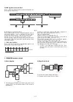
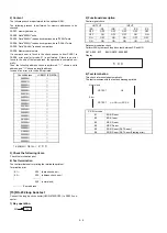
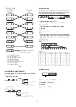
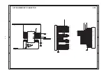
ECR-ER-02FD cable
Fig. 3-2
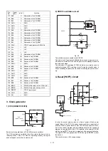
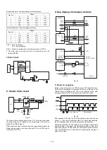
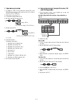
4. Application specification
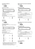
The following service (SRV) modes are available for the serial data
transfer of the ECR
1) Data transmit (Source side)
X: 0=SSP DATA
2) Data receive (Target)
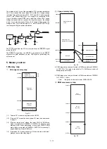
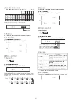
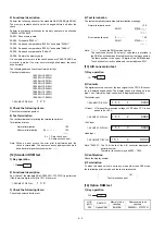
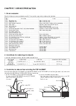
5. Data format
A single byte image of the RAM data to be transmitted is divided into a
high order 4 bits and low order 4 bits and converted into ASCII code.
Then, the image of the memory is sent in the following format:
1
Memory top address: 0000H
~
FFFFH
Top address of the memory to be transmitted in ASCII number.
2
Page:1F
~
27,00
Page of the memory to be transmitted in ASCII number.
3
Sum check
4
End code: Hex 0D
NOTE:
·
In order that contents of RAM memory may not over-ride pages for
this job, RAM image is sent in unit of 64 bytes from the address
0000. In other words, 128 bytes are sent at one time on the transmit
data format.
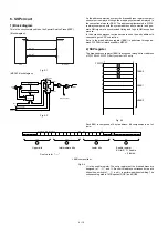
RAM DATA FORMAT
Exhibit:
Code table
HEX
ASCII
Character
HEX
ASCII
Character
0
30
0
8
38
8
1
31
1
9
39
9
2
32
2
A
41
A
3
33
3
B
42
B
4
34
4
C
43
C
5
35
5
D
44
D
6
36
6
E
45
E
7
37
7
F
46
F
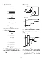
6. END record
1
End message:
Fixed to 30303030.
2
End massage:
Fixed to 4646.
3
Sum check
4
End code:
CR (0D)
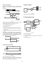
SD
2
SD
RD
CTS
RD
3
6
5
3
2
6
8
ER-02FD
7
5
SG
RTS
4
DCD
8
DTR
20
DSR
7
1
4
ECR
CTS
SG
RTS
DCD
DTR
DSR
1
FG
FRAME GROUND is connected
to the shield of the cable.
25PIN D-SUB
9PIN D-SUB
SD : TRANSMITTED DATA
RD : RECEIVED DATA
DTR: DATA TERMINAL READY
DSR: DATA SET READY
RTS: REQUEST TO SEND
DCD: DATA CARRIER DETECTOR
CTS: CLEAR TO SEND
FG : FRAME GROUND
996
X
TL
All data
X
ST
(Auto baud rate setting: ECR to ECR only)
(Baud rate setting: #903-A)
998
X
TL
(Auto baud rate setting: ECR to ECR only)
(Baud rate setting: #903-A)
ST
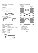
1
2
3
4
Data (128bytes)
BD
7E
83
FC
03
B6
42 44 37 45 38 33 46 43 30 33 42 36
30
3
4
30
30
30
1
2
6 – 2
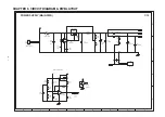
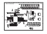
Summary of Contents for ER-A450
Page 51: ...MAIN PWB LAYOUT 1 SIDE A 8 15 ...
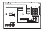
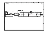
Page 52: ... 2 SIDE B 8 16 ...
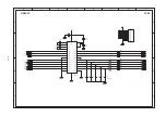
Page 53: ...PS PWB FRONT DISPLAY PWB POP UP DISPLAY PWB 8 17 ...