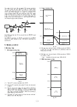


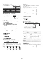


2) Content
The following check are performed for the optional RAM.
The following process is performed for memory addresses to be
checked.
PASS1: memory data save
PASS2: Data "0000H" write
PASS3: Data "0000H" read and comparison, data "5555H" write
PASS4: Data "5555H" read and comparison, data "AAAAH" write
PASS5: Data "AAAAH" read and comparison
PASS6: Memory data restore
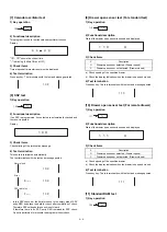
If a compare error is found in the check sequence from PASS1 to
PASS6, error print (error code E1) is performed. If there is no error
found to the end of the last address, the operation is completed nor-
mally.
Then the following address check is performed. "
|
" shows a valid
address, and "
✕
" shows an invalid address.
In case of an error, error code E2 is printed.
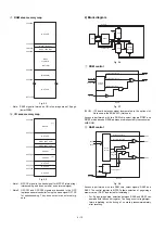
Check Address
JOB#201(ER-03RA)
200000H
|
200001H
|
200002H
|
200004H
|
200008H
|
200010H
|
200020H
|
200040H
|
200080H
|
200100H
|
200200H
|
200400H
|
200800H
|
201000H
|
202000H
|
204000H
|
208000H
|
210000H
|
220000H
|
240000H
|
260000H
|
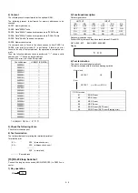
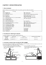
3) Check the following items.
Check the termination print.
4) Test termination
The test terminates after printing the termination printout.
Termination print
E1---
200
(data check error)
E2---
200
(address check error)
*****
200
(normal end)
******
: Error address
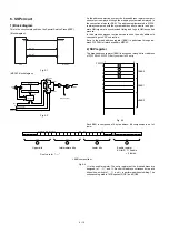
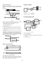
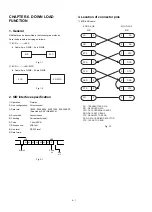
[15] RS-232 loop back test
Connect the loop back connector(UKOG-6705RCZZ) to RS232 con-
nector.
1) Key operation
2) Functional description
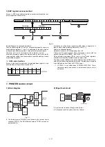
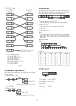
Control signal check
OUT PUT
INPUT
/ER
/RS
/DR
/CI
/CD
/CS
OFF
OFF
OFF
OFF
OFF
OFF
OFF
ON
OFF
OFF
ON
ON
ON
OFF
ON
ON
OFF
OFF
ON
ON
ON
ON
ON
ON
Data communication check
Perform 256-byte branch loop back test between SD and RD.
DATA: $00 - $FF
BAUD RATE: 9600 BPS
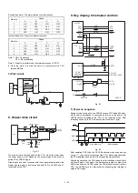
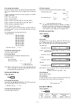
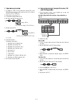
Display:
4) Test termination
This check is terminated automatically.
The test terminates with the test and message printed
XX: Error code
E1
ER-DR error
E2
ER-CI error
E3
RS-CD error
E4
RS-CS error
E5
SD-RD error (DATA error)
E6
SD-RD error (DATA error/Flaming error)
2
0
7-SEGMENT DISPLAY:
0
500
TL
5 0 0
Normal end
Error
NG
RS TEST
ER XX
RS TEST
OK
5 – 6
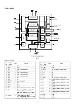
Summary of Contents for ER-A450
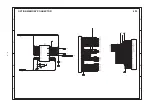
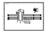
Page 51: ...MAIN PWB LAYOUT 1 SIDE A 8 15 ...
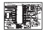
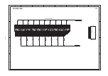
Page 52: ... 2 SIDE B 8 16 ...
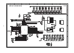
Page 53: ...PS PWB FRONT DISPLAY PWB POP UP DISPLAY PWB 8 17 ...