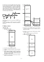
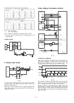


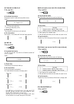
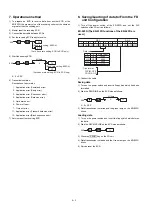


2) Power off sequence
When the CPU senses a service interruption, it performs necessary
procedures for CPU stop. Then the CPU outputs a reset request to the
CKDC8.
Reset request
Fig. 9-3
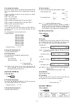
When the CPU senses a service interruption or an error, it performs
necessary procedure for CPU stop and issues reset request.
CPU procedures necessary for reset request
1
All CPU interrupts are made DI.
2
SCK is driven to low.
3
Keep LDRQ at LOW level for 20usec or more and drive it HIGH.
4
Loop
1
to
3
. During looping, access should not be made to
external memory.
5
It should be within 140usec from rising of one LDRQ to rising of
another.
When, however, the CKDC8 senses a service interruption at POF, it
stops displaying. Service interruption procedure is performed after re-
ceiving reset request from the CPU. If reset request is not sent from
the CPU within 100msec the service interruption procedure is started
after 110
±
10msec to go into the stand-by mode.
Fig. 9-4
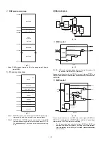
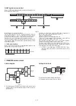
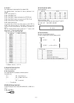
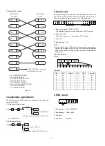
3) Key and switch scanning
Fig. 9-5
As the strobe signal, 8 bits of ST0 - 8 are used.
KR0 - KR7 are used as the key return signal. KR10 is used as the
return signal of the paper feed key, cashier key and MRS switch.
KR11 is used as the return signal of the mode switch.
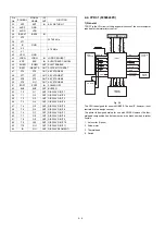
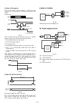
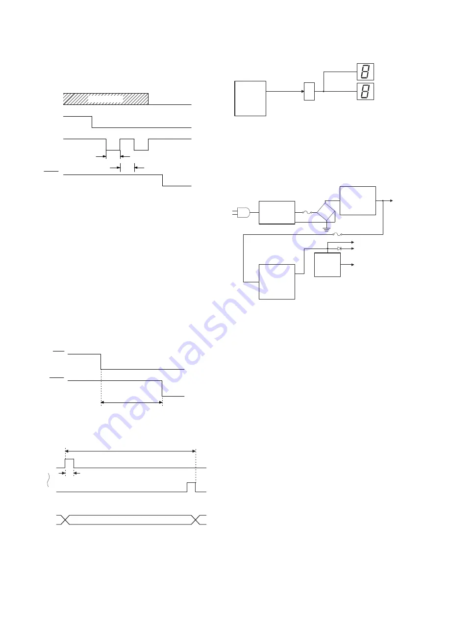
4) DISPLAY CONTROL
Fig. 9-6
CKDC8 directly drives the LED display unit.
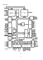
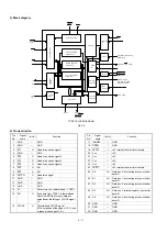
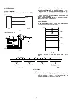
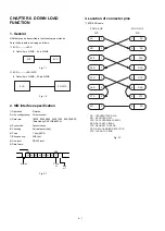
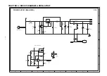
10. Power supply circuit
Fig. 10-1
+24V: Printer, solenoid power
+5V:
VCC (Logic power)
VDD: Battery charge, Battery back-uped power, CKDC-8 Back-up
power
VCH: Fiscal memory unit
20µsec or more
SCK
LDRQ
SHEN
DON'T CARE
TH
20µsec or more
TL
TL+TH 140µsec
<
=
RES1
POF
RES1
110±10msec
356.25µsec
38µsec
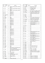
KR0~KR7
KR10,KR11
ST0
ST9
CKDC5
G1-G10
SA-SG,DP
LED-display
(for custmer)
LED-display
(for operator)
Driver
Power
trans.
DC-DC
Converter
circuit
Battery
circuit
+5V
F1
F2
Switching
regulator
+24V
+
-
~
~
VDD
VCH
4 – 19
Summary of Contents for ER-A450
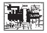
Page 51: ...MAIN PWB LAYOUT 1 SIDE A 8 15 ...
Page 52: ... 2 SIDE B 8 16 ...
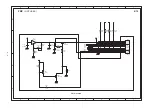
Page 53: ...PS PWB FRONT DISPLAY PWB POP UP DISPLAY PWB 8 17 ...