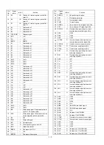


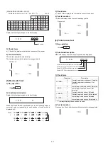

Receipt feed motor: The motor rotates counterclockwise.
Step No.
Phase
A
B
C
D
1
ON
OFF
ON
OFF
2
ON
OFF
OFF
ON
3
OFF
ON
OFF
ON
4
OFF
ON
ON
OFF
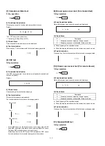
Journal feed motor: The motor rotates clockwise.
Step No.
Phase
A
B
C
D
1
ON
OFF
OFF
ON
2
ON
OFF
ON
OFF
3
OFF
ON
ON
OFF
4
OFF
ON
OFF
ON
Note 1: ON = Conducting
OFF = Not conducting
Note 2: Step No. is performed by the internal process of TPRC1.
·
When the motor is locked, the circuit is connected to the CPU
through MPCA6.
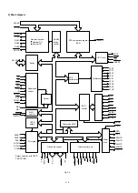
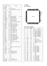
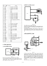
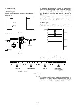
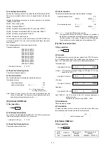
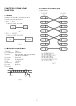
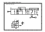
3) Print circuit
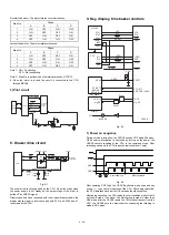
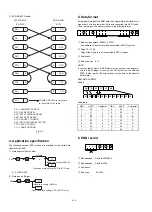
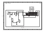
8. Drawer drive circuit
Fig. 8-1
The drawer is directly supported by the CPU. No action starts when
the power supply is not steady as the output stage of the driver is
pulled VP by VRESC signal.
Drawer open and close is sensed with the microswitch provided in the
drawer whose signal is level converted with R161 and R162 and di-
rectly read by the CPU.
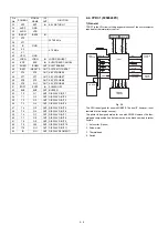
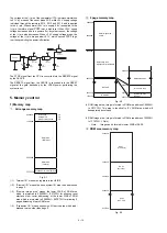
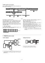
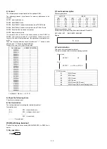
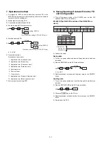
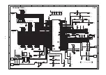
9. Key, display, time buzzer controls
Fig. 9-1
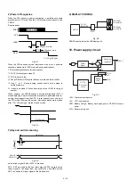
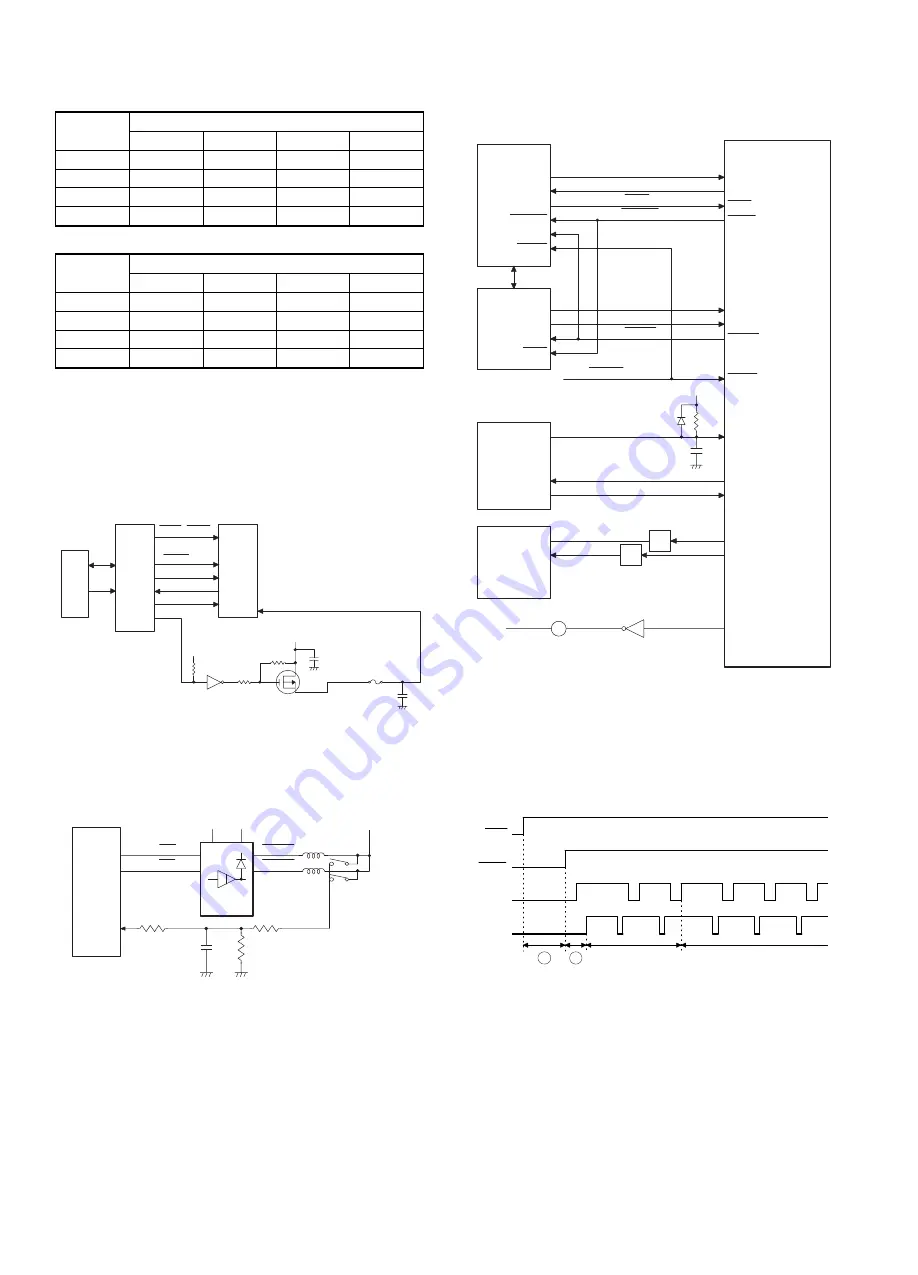
1) Power on sequence
During service interruption, the CKDC8 senses POF within 500msec.
When service interruption is cancelled by turning on the power, the
CKDC8 cancels resetting of the CPU in the command mode. After
initializing each port, the CPU reads the start condition (1 byte).
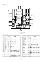
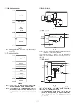
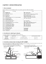
Fig. 9-2
After sampling POF High, the CKDC8 performs mode scan and key
scan at
1
, then cancels resetting of the CPU. After being cancelled,
the CPU initializes each port at
2
and reads the start condition.
After being cancelled, the CPU reads the start condition without fail to
set the sift mode. If, however, the first starting is made in other than
SRV mode after the CKDC8 resets the CPU without request from the
CPU, the CKDC8 sets the start condition supposing that starting is
made in SRV mode.
PB
RAM
TPRC 1
STRB1~STRB5
LATCH
SO
SI
CLOCK
VHCOM
VRES
Thermal
printer
head
VH
+24V
DR0
DRAW0
52
50
DOSP
C105
1000P
R162
4.7K
TD62308F
R161 22K
51
DR1
DRAW1
VRESC
CPU
+24V
Drawer
solenoid
+24V
R163
47K
IC9
KR0~7,KR10,KR11
ST0~ST7
ST0~ST7
G1~G10
T0~T9
RES0
RESET
VDD
RES0
a~g,DP
KR0~KR7
KR10,KR11
a~g,DP
Key board
Display
CKDC 8
VCC
B
BUZZER
2
Driver
Driver
HTS1
SCK1
RESET
INT2
POFF
HTS
SCK
RESET
HTS
SCK
RES1
CPU
MPCA7
STH1
STH
STH
P11
P12
RES
LDRQ
SHEN
LDRQ
SHEN
P10
ERC
ECR
P-OFF
POFF
POF
RES1
SHEN
LDRQ
1
2
Start condition
Next command
4 – 18
Summary of Contents for ER-A450
Page 51: ...MAIN PWB LAYOUT 1 SIDE A 8 15 ...
Page 52: ... 2 SIDE B 8 16 ...
Page 53: ...PS PWB FRONT DISPLAY PWB POP UP DISPLAY PWB 8 17 ...