DESCRIPTION
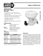
SANICOMPACT
®
Star
is a wall hung WC pan
fitted with a pump macerator.
The
SANICOMPACT
®
Star
can only be
installed with the special support brackets
supplied.
SANICOMPACT
®
Star
is for use in
a domestic environment.
Installed and used correctly,
SANICOMPACT
®
Star
will give reliable and consistent service.
Please note the following warning signs:
"
" Possible danger to personnel,
"
" Warning of possible electrical hazards,
"
WARNING
" This is a general warning that
failure to follow instructions could result in
poor functioning of the unit.
PRINCIPLES OF OPERATION
SANICOMPACT
®
Star
is controlled by an
electronic program with two functions.
• The cycle which is activated by pressing
the flushing button on the pan. The
macerating/pump cycle takes 25 seconds.
• The pumping only cycle cleans the
washbasin waste. This is an automatic
operation that will activate as long as water
from the washbasin enters the unit.
1
LIST OF ACCESSORIES SUPPLIED
2
DIMENSIONS
3
TECHNICAL DATA
Applications
évacuation WC
évacuation lave-mains
Type
C45
Maximum Vertical Pumping
3 m
Voltage 220-240
V
Frequency 50
Hz
Normal Power Rating
500 W
Maximum current consumption 2,5 A
Medium water temperature
35°C
Electric Class
I
Degree of protection
IP44
Net Weight (with frame)
28 Kg
WARNING:
Only installations conforming to
the above specifications are acceptable.
4
PERFORMANCE CURVE
5
VERTICAL/HORIZONTAL
PUMPING COMBINATIONS
6
INSTALLATION
PREPARATIONS
WARNING:
Before proceeding with the
installation of
SANICOMPACT
®
Star
, ensure
that the wall is sufficiently robust to support
the unit. (Each fixing should have a tensile
strength of 120 kg).
7
HANGING THE PAN ONTO THE
SUPPORT FRAME
1 -
Separate the pan and template
from
the frame (screwed together for transit
purpose).
- Assemble the threaded rods
with nuts
and washers
as per drawing 7a.
- Adjust the rod position to 50 mm + x the
wall thickness (eg. Stud partition and
tiles etc). See drawing 7a.
4 -
Adjust the lateral spacing of the rods.
5 -
Tighten the nuts fully.
6 -
Fit the plastic sleeves/inserts
onto
the threaded rods. (They protect the
ceramic from the metal threads).
SETTING THE HEIGHT OF THE
SUPPORT FRAME
- Offer the frame and pan up to the wall.
- Adjust to a comfortable height using the
vertical threaded feet. (See drawing 7b).
3 -
Remove the pan from the frame.
- Adjust the horizontal seating of the pan
support.
- Fully tighten the rod nuts.
FIXING THE FRAME TO THE WALL
1 -
Offer the support frame up to the wall.
2 -
Ensure the seating is correct.
- Mark the screw holes with a pencil.
-
WARNING:
If your wall is not perfectly
vertical, use the six holes with a suitable
combination of packing/washers (as per
drawing 7c).
5 -
Select the fixing appropriate for the
particular wall (we recommend minimum
size 8 x 120 mm wall fixings).
- Drill holes with appropriate drill.
- Fix the frame to the wall using the 4 or
6 holes accordingly.
-
WARNING:
The distance between the supporting
wall and the front of the support frame
should not exceed 100 mm.
Most importantly, the frame and the wall
should make a completely snug fit.
WATER SUPPLY
1 -
Run the water supply with copper pipe
in 15 mm, fitted with a 22 mm male iron
to connect to the
SANICOMPACT
®
Star
.
2 -
The water supply pipe must be fitted in
the upper part of the frame.
3 -
WARNING:
It is essential to install an
isolation valve when fitting the pan.
4 -
For correct rinsing of the bowl, the water
pressure entering the pan must be
minimum 1,7 bar.
7d
8
7
6
4
3
7c
5
4
2
1
7b
D
3
C
B
A
2
E
7a
UK
DISCHARGE CONNECTION
1 -
The discharge pipe should be either
copper or UPVC solvent weld pipe with
32 mm diameter.
2 -
Put the end of the pipe through the
upper part of the frame.
3 -
If the discharge pipework runs to a level
considerably lower than
SANICOMPACT
®
Star
unit, the resultant syphoning effect
can suck out the water seal in the unit.
Fitting an air admittance valve
(BBA approved) at the high point of the
pipe run will overcome this problem.
CONNECTION OF WASH-BASIN
1 -
Connect washbasin waste via 32 mm or
40 mm CPVC pipe.
2 -
Feed the waste pipe through either the
left or right hand holes provided.
3 -
IMPORTANT:
The waste pipe should
terminate in 40 mm to connect to the
special connector provided.
7g ELECTRIC POWER SUPPLY
The electrical installation work must be car-
ried out by a qualified person.
The electrical installation work for the
equipment, in a bathroom, must be carried
out in accordance with the standards in force
in the country (NF C 15-100 in France).
The electric power supply as wired
beforehand by the installer must be class 1,
using 3 X 0.75 sq. mm wiring.
1 – Connect the electric power supply to a
triple screw connector (not supplied) in
an
IP55 junction box (Sarel 01650 or
similar) installed beforehand, complying
with the following colours:
Brown = phase
Blue = neutral
Green/Yellow = earth.
2 – This connection must be used solely to
power the equipment, and it must be
protected by a high sensitivity 30mA
differential circuit breaker, set at 16 A.
3 -
ATTENTION:
the electrical junction box
must remain accessible after installation
of the toilet.
7f
7e
Fully illustrated step by step
instructions are downloadable
on www.saniflo.co.uk


