


Manual – Controllers DHE/DHF/DHR21B (standard) and DHE/DHF/DHR41B (advanced)
25
4
Installing the DH.21B/41B option
Assembly and Installation Notes
4.7.3
Connnection to system bus CAN 2 (X32) / CAN 1 (X33)
You can connect a maximum of 16 units to the DH21B option and a maximum of 64 units
to the DH.41B option on the CAN 2 or CAN 1 system bus. The system bus supports the
address range 0 to 63.
The CAN system bus supports transmission systems compliant with ISO 11898. The
"Serial Communication" manual contains detailed information on the system bus. This
manual can be ordered from SEW-EURODRIVE.
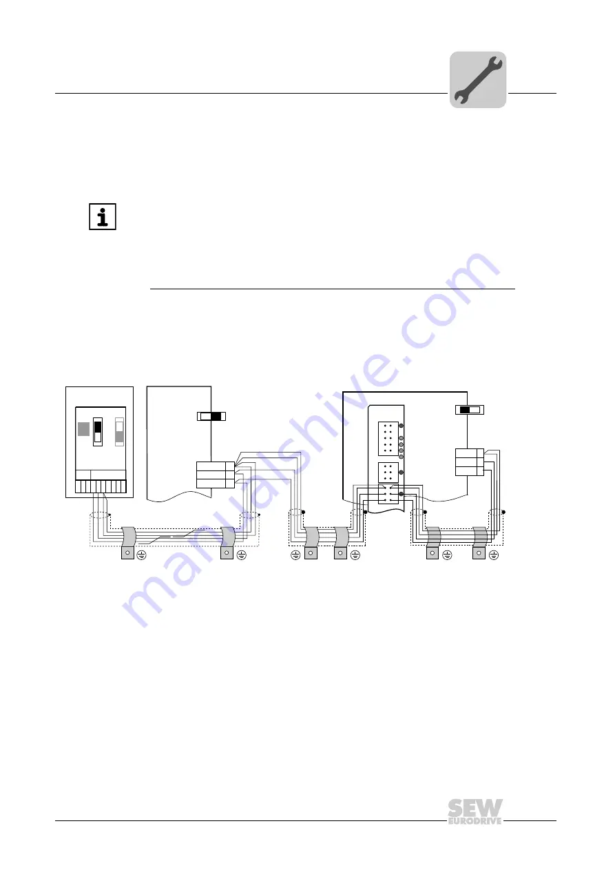
Wiring diagram for CAN 1 system bus
Cable specification
•
Use a 2 × 2-core twisted and shielded copper cable (data transmission cable with
braided copper shield). Clamping without conductor end sleeves is possible in
accordance with IEC 60999. The cable must meet the following specifications:
– Cable cross section 0.2 mm
2
– 1.0 mm
2
(AWG24 – AWG18)
– Cable resistance 120
Ω
at 1 MHz
– Capacitance per unit length
≤
40 pF/m at 1 kHz
Suitable cables include CAN bus or DeviceNet cables.
INFORMATION
•
The CAN 2 system bus is electrically isolated. We therefore recommend to use
the CAN 2 ( X32) interface for connecting field devices (e.g. CANopen inputs and
outputs).
•
The CAN 1 system bus is
not
electrically isolated. We therefore recommend to
use the CAN 1(X33) interface to connect inverters via the system bus in the
control cabinet.
•
A system CAN connection is required for communication between
MOVIDRIVE
®
MDX61B and the integrated controller.
2102461835
MDX61B
DGND
MDX60B/61B
X12
SC11
2
1
3
SC12
DHE41B
X31
X32
X33
1
2
3
1
2
3
1
2
3
2
3
1
SC11
DGND
ON
OFF
S12
X12:
2
1
SC12
3
ON
OFF
S12
X45
X46
1 2 3 4 5 6
H L
⊥
FSC11B
MOVITRAC
®
B
S1
OFF
ON
7
S2
X44
Buy: www.ValinOnline.com | Phone 844-385-3099 | Email: [email protected]