


Drive Technology \ Drive Automation \ System Integration \ Services
Manual
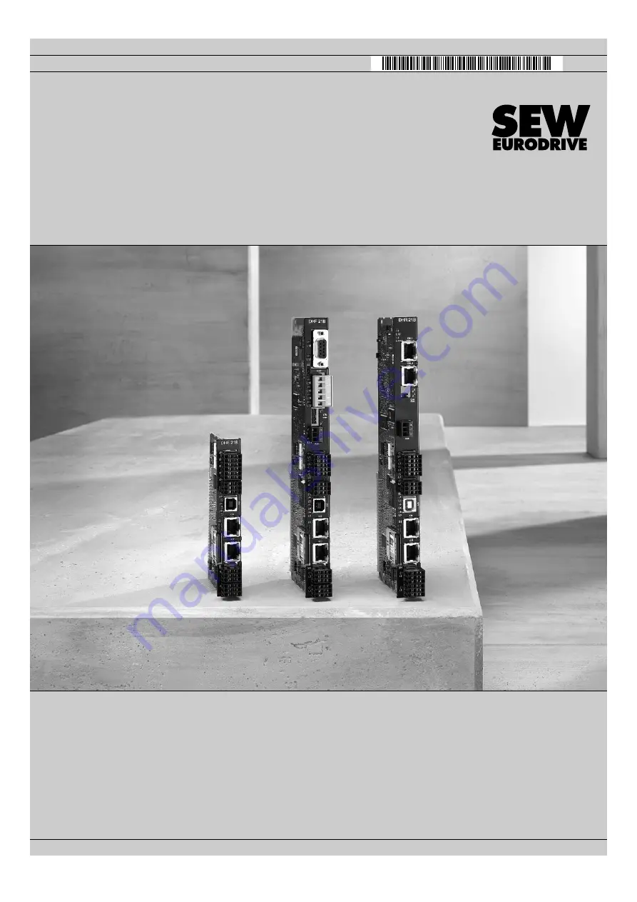
Controllers
DHE21B / DHF21B / DHR21B (standard)
DHE41B / DHF41B / DHR41B (advanced)
Edition 03/2010
16897226 / EN
Buy: www.ValinOnline.com | Phone 844-385-3099 | Email: [email protected]